
An UAV fixed point hover system and method

a technology of fixed point hover and hover system, which is applied in the field of unmanned aerial vehicles (uav), can solve the problems of low popularity of fixed point hover technology, large system error of innertial navigation system, and low accuracy rate of fixed point hover

Inactive Publication Date: 2020-03-26
BEIJING UNIV OF TECH
View PDF0 Cites 4 Cited by
  • Summary
  • Abstract
  • Description
  • Claims
  • Application Information

AI Technical Summary

Benefits of technology

The invention reduces the time and effort required to calculate the movement of light, making it more efficient and stable. This is compared to existing technology.

Problems solved by technology

However, due to the low refresh frequency of low-cost GPS data, the data provided by it will cause serious lag of attitude compensation command of the airframe in the narrow space or when the UAV moves at high speed which lead to serious consequences such as plane crash.
However, after a long flight, the inertial navigation system will produce a large system error.
The longer the flight time, the larger the error will be, and the accuracy rate of fixed point hover will decrease greatly.
This method is more accurate than GPS fixed point method, but it is expensive and requires a lot of base station and laser emission equipment to be deployed in advance, so the popularity of this technology is not high.
This method does not need the assistance of external transmitting signal, so it has a wide range of application and a small system error, but it needs to calculate the light flow information of the whole image, the calculation amount is too large for the UAV's onboard processor to bear which will lower the calculation efficiency, and the control signal will be seriously delayed.
Any small delay in flight can lead to serious consequences, so the practicability of this method needs to be improved.
(1) Indoor positioning device (CN201620160519.0): an indoor positioning device, located on a UAV, comprising: ultrasonic emitting PCB board, ultrasonic receiving PCB board and optical flow PCB board, optical flow PCB board includes optical flow camera and microcontrol unit MCU, ultrasonic transmitter: generate and emit ultrasonic wave under the control of MCU on optical flow PCB; ultrasonic receiving board: sending ultrasonic wave to MCU on optical flow PCB board when receiving ultrasonic wave; optical flow camera: take images of the ground and transmit them to the MCU; MCU: control the ultrasonic emission of PCB board and start the timing. When the ultrasonic wave is received stop the timing and calculate the height of the UAV according to the time; The displacement of the UAV in the horizontal x direction and the vertical y direction on the ground is calculated according to the ground image from the optical flow camera. This device has too many components and high manufacturing cost. By attaching computers and a large number of auxiliary parts to improve the timeliness of optical flow positioning, the cost is too high and the problem of excessive calculation of optical flow algorithm cannot be solved.
(2) An UAV speed monitoring method and system (CN201610529291.2): an UAV speed monitoring method and system comprising: obtain the current flight altitude, angular velocity and image; obtain the feature points of the image and calculate the light flow of each feature point; count the optical flow of each feature point, select the optical flow with the highest repetition rate in the same direction as the optical flow of the image; Calculate the current flight speed according to the flight altitude, angular velocity and the light flow of the image. The invention also relates to a system corresponding to its UAV speed monitoring method. The optical flow of each feature point is calculated by obtaining the feature points of the current image through calculation, and the optical flow with the highest repetition rate of optical flow in the same direction is selected as the optical flow of the image. Then, the current flight speed is calculated according to the current flight height and angular velocity of the optical flow of the image. The calculation is simple, the computational amount is small, and the influence of multiple factors is taken into account, so the calculation result is accurate.
As a detection method, it fails to organically combine with the whole UAV to control the UAV's movement and attitude, so it cannot be effectively applied to the fixed point hovering of the UAV.
Traditional light flow fixed point method does not consider the texture feature, but calculates the light flow of the entire image, so the calculation amount is large, which affects the timeliness.

Method used

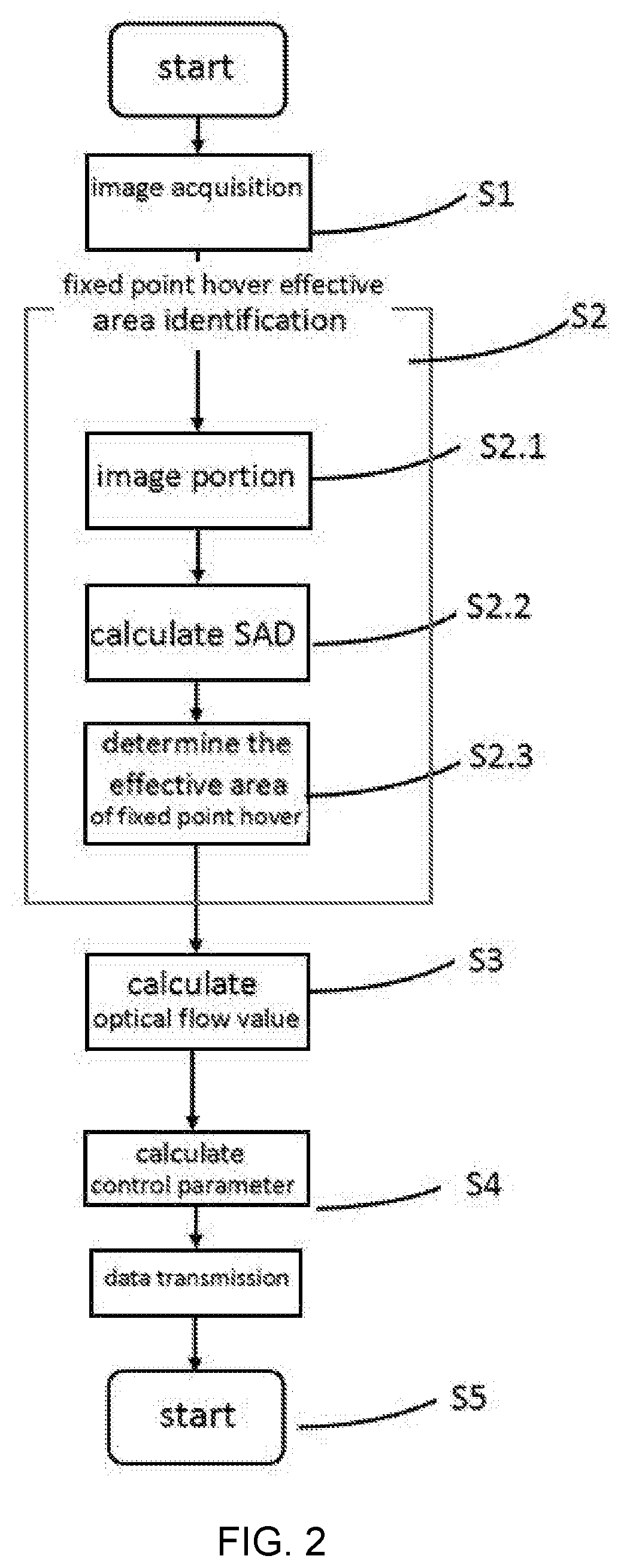

Image

  • An UAV fixed point hover system and method
  • An UAV fixed point hover system and method
  • An UAV fixed point hover system and method

Examples


Embodiment Construction

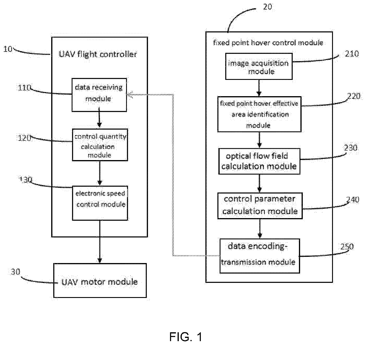
[0045]The embodiment of the invention is shown in FIG. 1 as a UAV fixed point hover system, including UAV flight controller 10, fixed point hover control module 20 and UAV motor module 30.

[0046]UAV flight controller 10 is used to control the flight of UAV; fixed point hover control module 20 is used to control fixed point hover in UAV flight; motor module 30 is used to change the flight motion state of UAV. UAV flight controller 10 includes data receiving module 110, control quantity calculation module 120 and electronic speed control module 130.

[0047]Data receiving module 110 is used to receive acceleration control variables sent by fixed point hover control module 20 and send them to control quantity calculation module 120; The control quantity calculation module 120 receives the control acceleration signal from the data receiving module 110, calculates the PWM waveform parameters needed to be generated according to the received control acceleration data, and then sends them to th...


PUM


Abstract

The invention relates to the field of unmanned aerial vehicle (UAV), and especially relates to a UAV fixed point hover system and method which can be used in indoor environment. The system comprising UAV UAV flight controller, fixed point hover control module and UAV motor module. UAV flight controller is used to control the flight of UAV; fixed point hover control module is used to control fixed point hover in UAV flight; motor module is used to change the flight motion state of UAV. The system provided by the invention includes a UAV system and method for UAV flight control, motor and fixed point hover control module. In fixed point hover control module, texture features are used to obtain effective areas, compared with the traditional fixed-point optical flow method, the computation is reduced. Then optical flow field is calculated by using optical flow method for above effective areas, to obtain the information of control acceleration.

Description

TECHNICAL FIELD[0001]The invention relates to the field of unmanned aerial vehicle (UAV), and especially relates to a UAV fixed point hover system and method which can be used in indoor environment.BACKGROUND ART[0002]With the development of economy and the continuous progress of science and technology, the research on UAV is getting deeper and deeper, it is widely used in aerial photography, mobile detection and security. The stability, accuracy and fast hovering ability of UAV flight platform have a very important influence on these fields.[0003]UAV fixed point hover is defined as: through the autonomous flight function or the remote control device of the UAV to control the UAV stay in the designated position in the air for a certain time.[0004]At present, the most mature and widely used method of UAV fixed point hover is GPS +barometer+gyroscope Integrated navigation system. The barometer is used to measure the height change, and the GPS module gives the coordinates of the horizo...

Claims


Application Information

Patent Timeline
IPC IPC(8): G05D1/08B64C39/02G05D1/00G06T7/40G06T7/246G06T7/73G06T7/11
CPCG06T7/11G06T2207/20021G06T2207/10016G05D1/0816B64C2201/141G06T7/40G05D1/0088G06T7/73G06T7/246G06T2207/10032B64C39/024B64U50/19G05D1/102G06T7/269G06T7/41B64U2201/10B64U2101/70B64U2101/30B64U2201/20
Inventor ZHANG, WENLIMA, YINGXUANFENG, HAOGUO, XIANG
Owner BEIJING UNIV OF TECH
Learn More