Control apparatus for controlling switching power supply

a control apparatus and power supply technology, applied in the direction of electric variable regulation, process and machine control, instruments, etc., can solve the problems of unstable burst frequency, unacceptably large noise at this frequency, and loss of continuity of burst frequency

Active Publication Date: 2020-04-02
FUJI ELECTRIC CO LTD
View PDF5 Cites 3 Cited by
  • Summary
  • Abstract
  • Description
  • Claims
  • Application Information

AI Technical Summary

Benefits of technology

The patent is about a control system for a switching power supply that includes a current resonance converter and can efficiently control a light load while also reducing noise. The system uses burst control to achieve high efficiency.

Problems solved by technology

When this happens, a current of 20 Hz to 20 kHz flowing in the transformer causes magnetostrictive noise at the transformer core, resulting in audible noise.
When conventional burst control is performed under a light load, the burst frequency is around 1 kHz and the noise at this frequency is unacceptably large.
When different numbers of resonance cycles coexist in this way, the burst frequency loses continuity and becomes unstable.
The coexistence of different numbers of resonance cycles results in a plurality of overlapping waveforms, and even when the respective periods of the different numbers of resonance cycles do not fall within the audible range, a component in the audible range may still result from a Fourier transform, leading to situations where the tolerated range for noise is exceeded.

Method used


Image

  • Control apparatus for controlling switching power supply
  • Control apparatus for controlling switching power supply
  • Control apparatus for controlling switching power supply

Examples


Embodiment Construction

[0025]Several embodiments will be described below with reference to the accompanying drawings. Note that parts denoted by the same reference numerals in the drawings indicate the same component elements. In the following description also, the same character strings may be used both for the names of terminals of component elements and voltages, signals, and the like at these terminals.

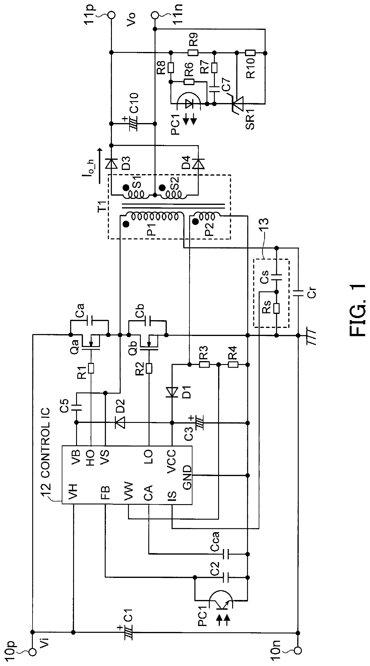
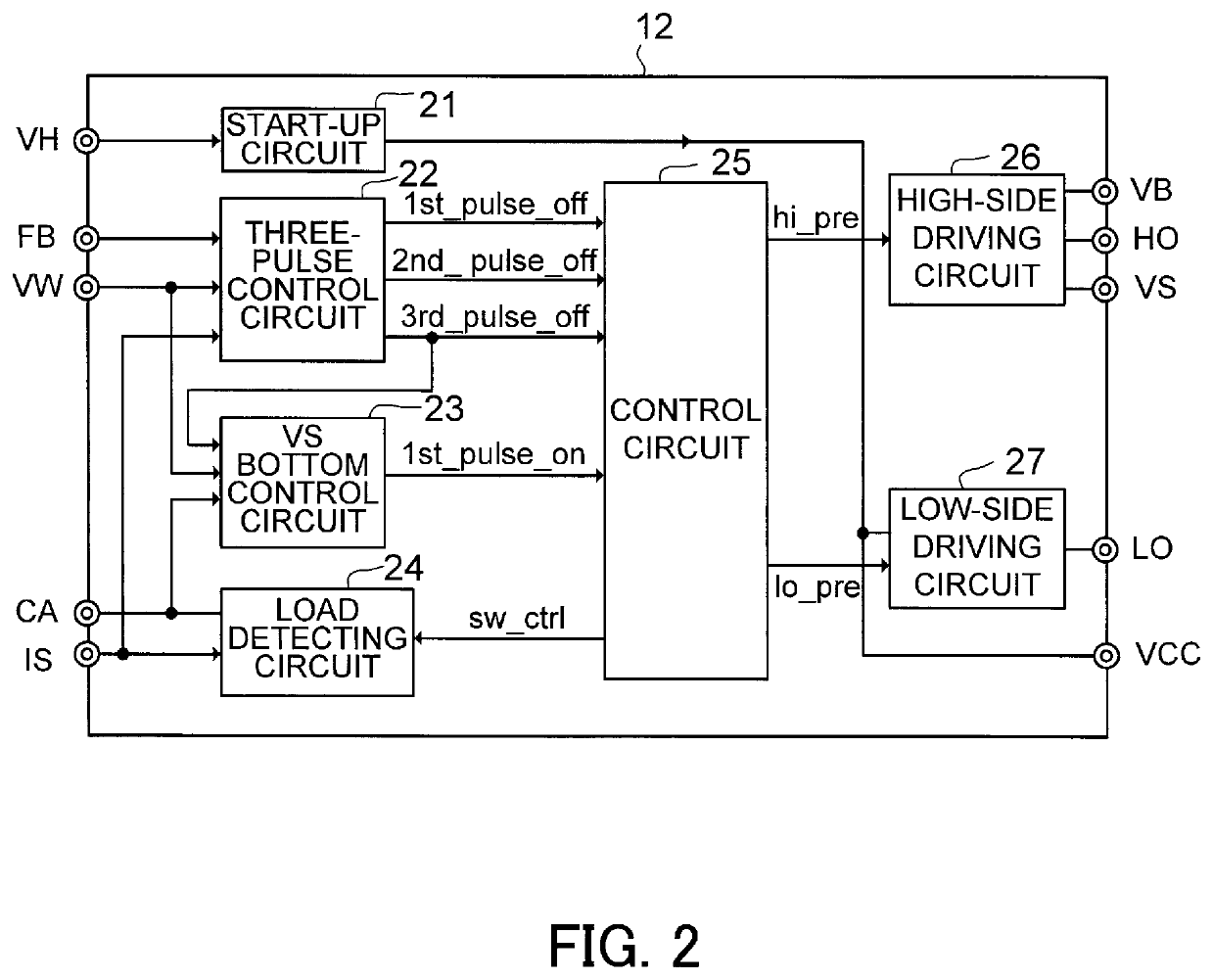
[0026]FIG. 1 is a circuit diagram depicting a switching power supply equipped with a control apparatus according to a first embodiment. FIG. 2 is a functional block diagram depicting an example configuration of a control IC as a control apparatus according to the first embodiment.

[0027]The switching power supply depicted in FIG. 1 includes input terminals 10p and 10n to which a direct current (DC) input voltage Vi is applied. As one example, the DC input voltage Vi is a high voltage that is constant and is generated by a power factor correction circuit. An input capacitor C1 and a half bridge circuit, w...


PUM


Abstract

An apparatus for controlling a switching power supply during burst control that includes a switching period and a no switching period. The switching power supply includes first and second switching elements and a resonance circuit. The control apparatus includes a load detecting circuit that shunts and averages a resonance current of the resonance circuit, an off signal generating circuit that generates off signals for turning off the first and second switching elements during the switching period, an on signal generating circuit that obtains a number of resonance cycles of the ringing voltage in the no switching period and generates a first pulse on signal for turning on the second switching element to restart the switching period, and a control circuit that receives the off signals and the first pulse on signal, and generates first and second control signals for alternating on-off control of the first and second switching elements.

Description

CROSS-REFERENCE TO RELATED APPLICATIONS[0001]This application is based upon and claims the benefits of priority of the prior Japanese Patent Application No. 2018-187435, filed on Oct. 2, 2018, and the Japanese Patent Application No. 2019-004420, filed on Jan. 15, 2019, the entire contents of which are incorporated herein by reference.BACKGROUND OF THE INVENTION1. Field of the Invention[0002]The embodiments discussed herein are related to a control apparatus for controlling a switching power supply that includes a current resonance-type direct current to direct current (DC-DC) switching converter and is capable of burst control that achieves high efficiency during a light load and also suppresses noise.2. Background of the Related Art[0003]Current resonance-type DC-DC switching converters achieve high efficiency and are capable of being miniaturized, which has resulted in widespread use in power adaptors for TVs and other devices, light emitting diode (LED) light fittings, and the li...

Claims


Application Information

Patent Timeline
IPC IPC(8): H02M3/335
CPCH02M2001/0009H02M3/33507H02M3/28H02M3/33523H02M1/14H02M1/0038H02M3/01H02M3/33571Y02B70/10H02M1/0035H02M1/0009H02M1/0058
Inventor YOSHIZAWA, TSUYOSHICHEN, JIAN
Owner FUJI ELECTRIC CO LTD
Why Eureka
Try Eureka