Tool manufacturing method

Active Publication Date: 2020-04-23
TEKTON
View PDF0 Cites 4 Cited by
  • Summary
  • Abstract
  • Description
  • Claims
  • Application Information

AI Technical Summary

Benefits of technology

[0016]In one embodiment, the present invention provides an angle-head wrench in which the centerline of the wrench jaw is significantly offset from the longitudinal centerline of the handle. The offset relationship between the handle and the wrench jaw may make it easier to fit to nuts or bolts situated in tight confines. In one embodiment, the wrench jaw is maximally offset or fully offset to enhance this feature to the greatest possible degree. For example, the wrench jaw may be offset such that the outermost edge of the beam is substantially aligned or substantially flush with the corresponding edge of the handle. In a typical application of this feature, the wrench jaw and the handle may be offset such that the longitudinal edge of the handle is essentially tangent to the curved-outermost edge of the beam.
[0017]The present invention provides an improved process to make a wrench or other hand tool used to apply force to fasteners that provides at least the strength, durability, and functionality of traditional forged wrenches, except using rolled steel (of various possible alloys) that is c

Problems solved by technology

The press or hammer requires expensive tools and dies which are unique to a single part.
Like forging, broaching requires expensive custom tooling for each size desired.
At lower volumes, forge and broach tooling costs can take many years or even decades to offset.
For example, there are meaningful practical limitations on the shapes that can be formed using conventional forging processes.
Shapes created in a forging process are limited to how far the mold can stretch or smash the metal.
For example, the capital letter “T” would be very

Method used


Image

  • Tool manufacturing method
  • Tool manufacturing method
  • Tool manufacturing method

Examples


Embodiment Construction

Overview

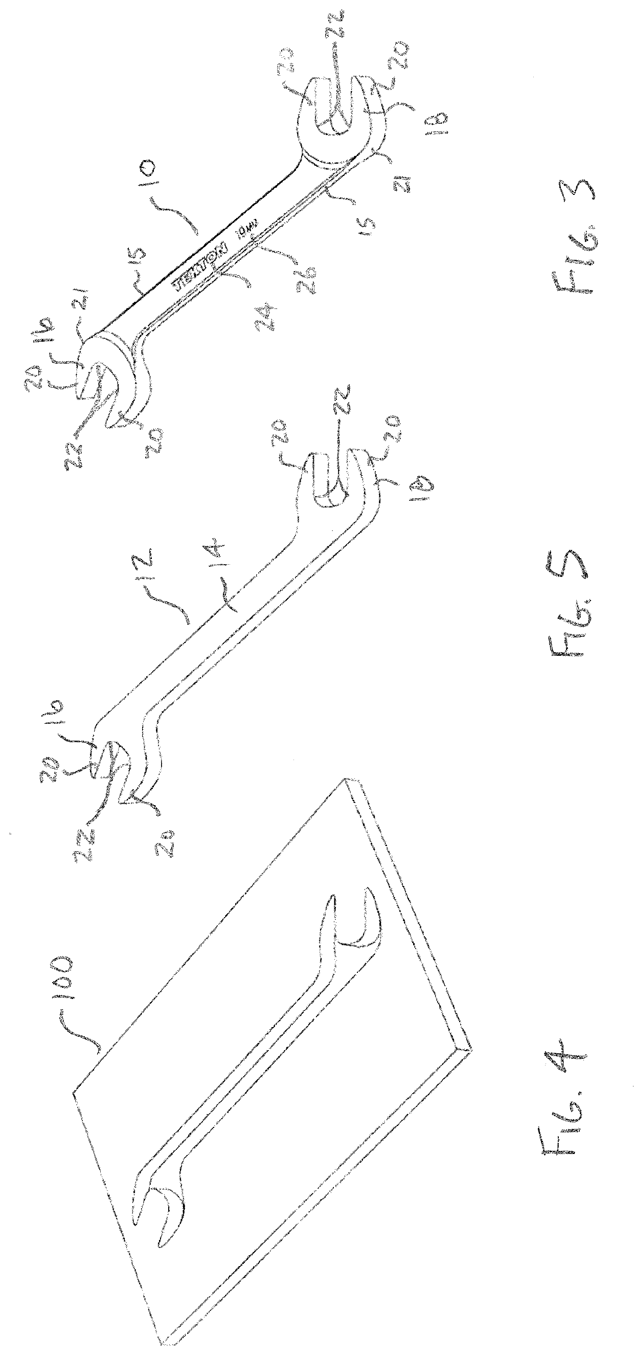
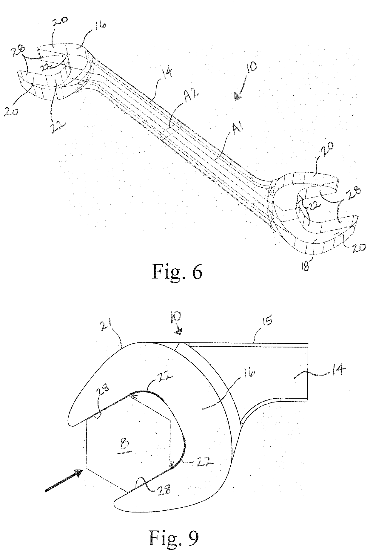
[0029]The present invention is directed to a method for manufacturing hand tools. In the illustrated embodiment, the method includes the general steps of providing a flat stock 100, such as sheet or plate stock, having a thickness that is at least equal to the maximum thickness of the tool; laser cutting the sheet or plate stock 100 to form a tool blank 12 by cutting the general two-dimensional shape of the tool; and three-dimensionally shaping the tool blank 12 into a three-dimensional workpiece 10 using one or more machining operations that give the tool blank the desired three-dimensional shape. After laser-cutting, the method may include supplemental sanding and / or grinding steps that remove any irregularities resulting from the laser cutting process and help to provide the tool blank 12 or three-dimensional workpiece 10 with desired final shape and surface quality. The method may also include the step of heat treating the tool blank 12 or three-dimensional workpiece 10 ...


PUM

PropertyMeasurementUnit
Angleaaaaaaaaaa
Thicknessaaaaaaaaaa
Forceaaaaaaaaaa

Abstract

A method for manufacturing hand tools, such as wrenches. The method generally includes the steps of providing a flat stock, cutting the flat stock into the desired two-dimension blank using a laser, and three-dimensionally machining the laser-cut 2D blank into the desired three-dimensional workpiece. The tool may undergo a heating treatment process and a surface treatment process. In the context of a wrench, the blank may be laser cut with a laser beam oriented to cut generally perpendicularly to the plane of the flat stock. After laser cutting, the handle and interface region between the handle and jaw(s) are machined to provide the desired three-dimensional shape. For example, the three-dimensional shape may be selected to provide a comfortable grip even when applying a high level of force. The wrench jaw may have an optimized geometry calculated so that there is no excess material or “over-designed” regions of the jaw. The wrench jaw has internal corners with optimized radii.

Description

BACKGROUND OF THE INVENTION[0001]The present invention relates to tools, such as wrenches, and more particularly to methods for manufacturing tools.[0002]It is a long-held and well-accepted belief that certain hand tools must be made using a forging process. For example, it is universally believed that wrenches of adequate function and strength must be manufactured through forging. Conventional wisdom is that forging is required to form a strong, high quality, general purpose wrench, such as a mechanic might use day to day. This belief has long been held not only by users of wrenches, but also by manufacturers of wrenches and, despite advancements in manufacturing technologies, this belief continues to be held to this day.[0003]Forging can be done using a forging press or forging hammer. FIG. 1 shows a conventional forged combination wrench manufactured in accordance with the prior art. The forged wrench of FIG. 1 is typically manufactured from a bar stock, such as the cylindrical b...

Claims


Application Information

Patent Timeline
IPC IPC(8): B25B13/08B23K26/08B23P15/00B25B23/16
CPCB23K2103/04B25B13/08B25B23/16B23K2101/20B23P15/00B23K26/0876B23K26/08B23K26/38B23K26/40B25B13/04
Inventor AMASH, JOHN A.BHUYAN, CODIE A.FASSEZKE, ETHAN D.HARRISON, BENJAMIN E.HENIGE, DEVIN L.MURPHY, LAURA R.
Owner TEKTON
Why Eureka
Try Eureka