
Assembled wire, method of manufacturing assembled wire and segment coil

a technology of assembled wire and wire, which is applied in the direction of insulating conductors/cables, cables, cables, etc., can solve the problems of inability to obtain the effect of separating the conductor, the influence of eddy current cannot be suppressed, and the winding loss may become larger, so as to improve the fill factor of the slot, reduce the deformation, and improve the effect of heat resistan

Active Publication Date: 2020-04-23
ESSEX FURUKAWA MAGNET WIRE JAPAN CO LTD
View PDF0 Cites 2 Cited by
  • Summary
  • Abstract
  • Description
  • Claims
  • Application Information

AI Technical Summary

Benefits of technology

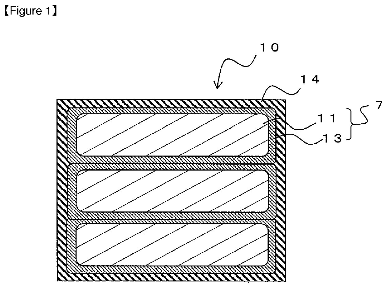
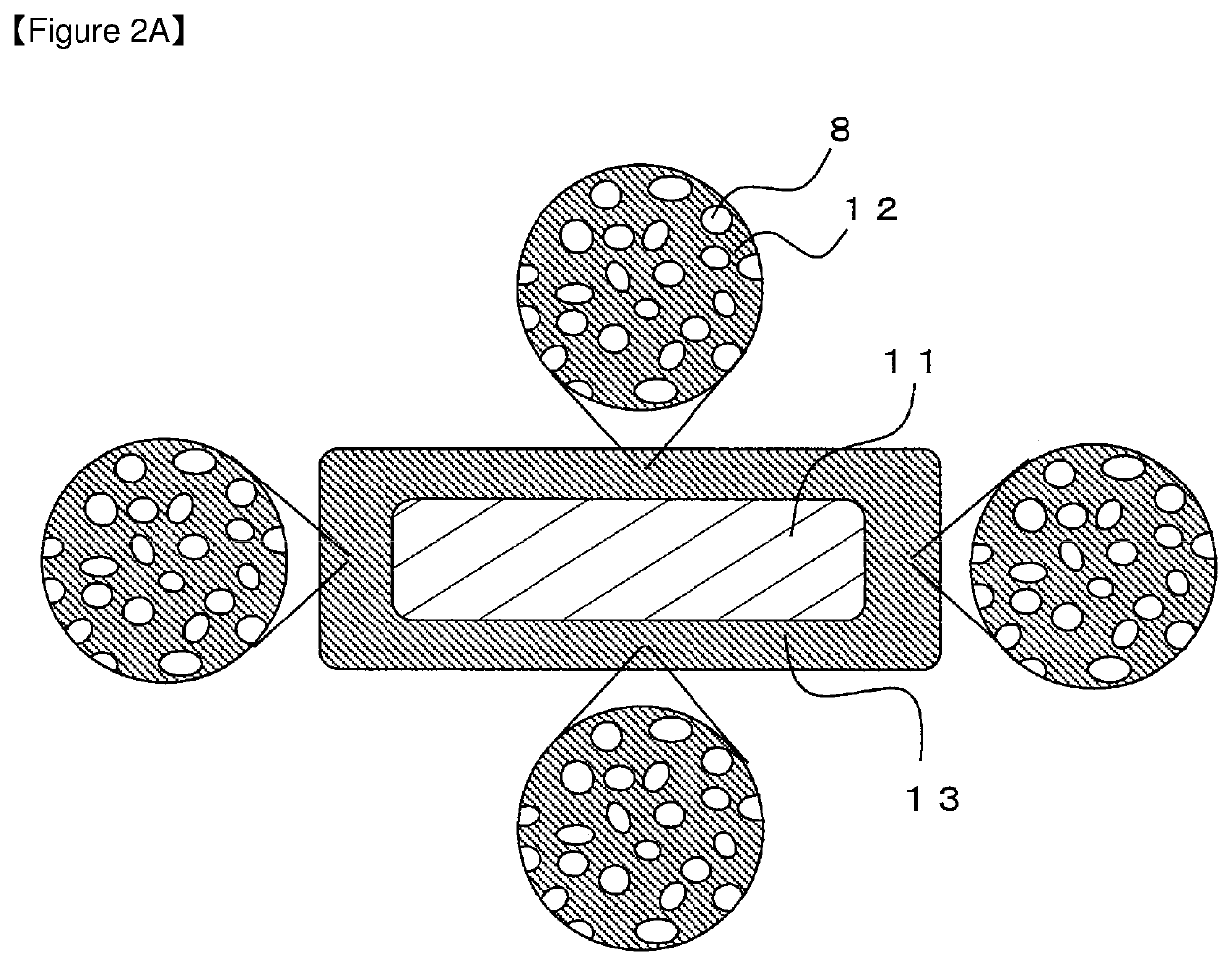
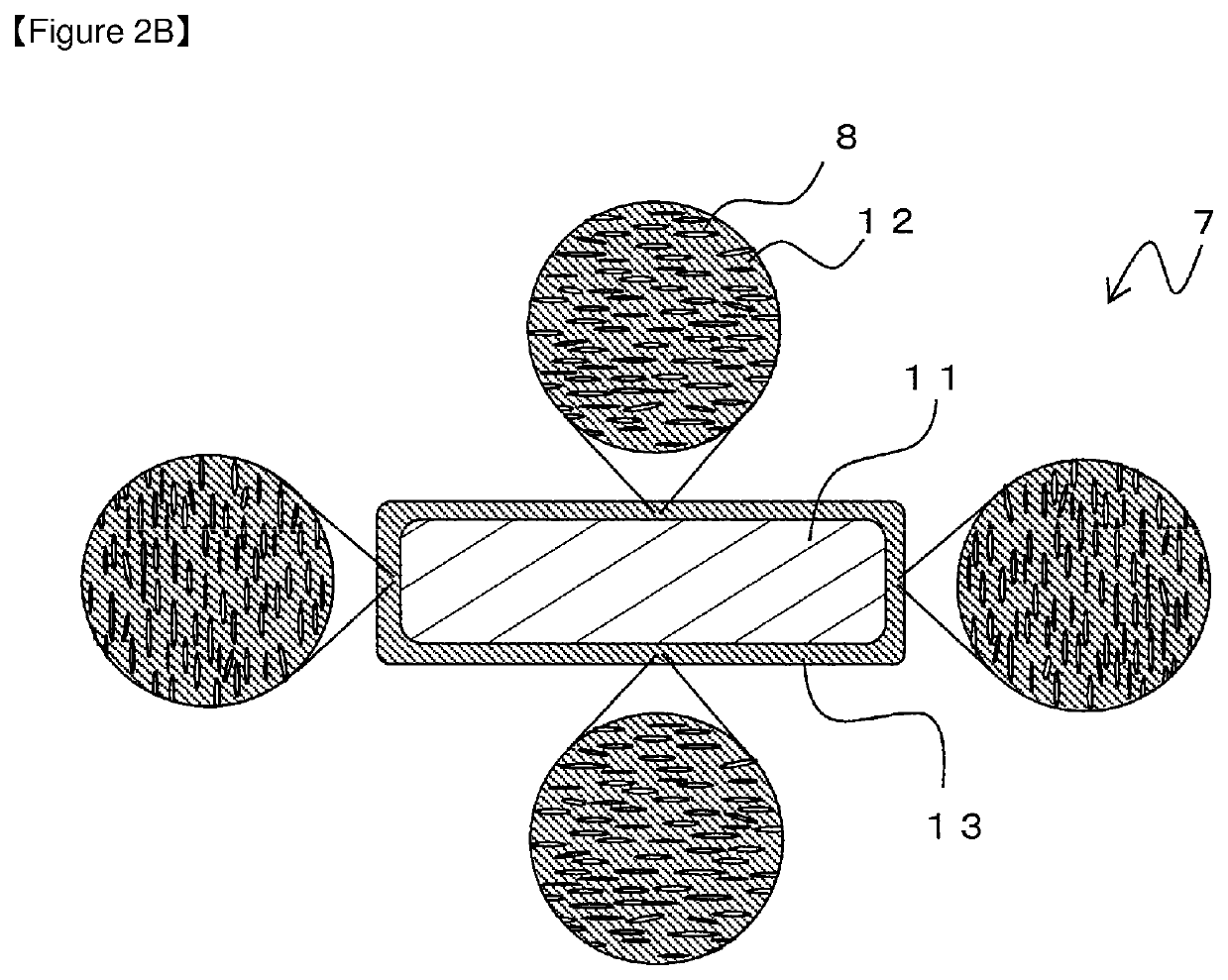
The first invention allows for easier manufacturing and improved performance of a welded segment coil by creating voids in the wire-element insulating layer, which allows for easy collapsing and deformation of the strand insulating layer. This results in a better fill factor and easier detachment of the strand insulating layer. The second invention provides a reliable segment coil design by eliminating the need for a separate reinforced part and solving issues with current designs.

Problems solved by technology

However, each flat winding wire has a large cross sectional area, and this leads to a problem that a winding loss may become larger due to eddy current generated when a frequency of the motor is increased due to increased rotational frequency of the motor.
If the strands are electrically conductive to each other, the influence of the eddy current cannot be suppressed and effects of separating the conductor cannot be obtained.
However, it is difficult to evenly coat a thin insulating layer on an outer periphery of a conductor.
If there is a part to which a coating is not applied due to inequality of coating thickness, insulating performance is not fully exhibited and, as mentioned above, the influence of the eddy current cannot be suppressed and effects of separating the conductor cannot be obtained.
However, simply increasing the thickness of the insulating layer decreases the cross sectional areas of the conductor portion, which reduces the fill factor of the conductor to the slot of the stator.

Method used


Image

  • Assembled wire, method of manufacturing assembled wire and segment coil
  • Assembled wire, method of manufacturing assembled wire and segment coil
  • Assembled wire, method of manufacturing assembled wire and segment coil

Examples


working examples

[0069]Next, a plurality of types of separated conductors with different strand insulating layers and the like are made and evaluated in high frequency performance, processability, and heat aging resistance. Working examples 1 to 11 according to the present invention are shown in Table 1 and Table 2. Also, comparison examples 1 to 4 are shown in Table 3.

TABLE 1WorkingWorkingWorkingWorkingWorkingWorkingExample 1Example 2Example 3Example 4Example 5Example 6MetalTypeCuCuCuCuCuCuConductorAssemblingStackedStackedStackedSeparation AStackedStackedMethodLayerLayerLayerLayerLayerNumber of226726SeparationType ofResinPAIPIPEIPAIPETPIstrandCoating3.04.02.52.54.02.5insulatingThicknesslayer(um)Cavity Ratio303045303555(Volume %)Type ofResinPEEKPPSPEEKThermo-PPSPEEKouterplastic PIinsulatingCoating100801508040120layerThickness(um)High FrequencyBBAABAPerFormanceSpace Factor99.198.898.098.098.998.0ProcessabilityBBBCBBHeat Aging ResistanceAAAABA

TABLE 2WorkingWorkingWorkingWorkingWorkingExampleExample 7E...


PUM

PropertyMeasurementUnit
Temperatureaaaaaaaaaa
Fractionaaaaaaaaaa
Fractionaaaaaaaaaa

Abstract

An assembled wire has a substantially rectangular cross section, and is formed by assembling a plurality of strands. Each strand has a conductor portion and a strand insulating layer covering the conductor portion. At least a part of the assembled plurality of strands in the longitudinal direction is covered with an outer insulating layer. The strand is formed as follows. First, the strand insulating layer is coated on the outer periphery of the conductor portion. At this time, a large number of voids are formed in a resin constituting the strand insulating layer. From this state, the strand is formed, for example, by collapsing the strand insulating layer by heating and pressurizing. At this time, it is possible to uniformly collapse the strand insulating layer by crushing the internal voids. Therefore, the voids in the strand are crushed and flattened in the thickness direction of the strand insulating layer over the entire periphery.

Description

TECHNICAL FIELD OF THE INVENTION[0001]The present invention relates to an assembled wire that can be used for a segment coil in a motor, for example, and the like.BACKGROUND OF THE INVENTION[0002]In a stator of a motor used in a car, for example, enamel wires with circular cross sections have been conventionally used as winding wires. However, in recent years, to improve a space factor, use of flat winding wires having rectangular cross sections has been increasing. Also, a manufacturing method in which winding wires are wound around a core of a stator has been conventionally adopted in many cases. However, with adoption of the flat winding wires, a method of forming a coil by forming winding wires into segment coils of short length, installing the segment coils to a stator, and then connecting terminal portions of the segment coils with each other by welding have been increasingly adopted.[0003]However, each flat winding wire has a large cross sectional area, and this leads to a pr...

Claims


Application Information

Patent Timeline
IPC IPC(8): H01B7/28H01B7/29H01B3/30H02K15/10H02K3/12H01F27/28H01B7/08H02K3/34
CPCH01B3/307H01B3/308H02K15/105H02K3/34H01F27/2823H01B3/306H02K3/12H01B7/08H01B7/2813H01B7/292H01F5/06H02K3/30H01B7/0233H01B7/02H01B5/06H01B3/30H01B7/0009H01B13/06H02K3/04H02K3/345
Inventor IKEDA, KEISUKETOMIZAWA, KEIICHIMUTO, DAISUKEFUKUDA, HIDEO
Owner ESSEX FURUKAWA MAGNET WIRE JAPAN CO LTD
Learn More