Slide member and method for manufacturing same

a technology of sliding member and manufacturing method, which is applied in the direction of engine components, mechanical apparatus, cylinders, etc., can solve the problems of fatigue crack generation, difficulty in removal, and low strength of the region in the vicinity of the bonding interface where the bi phases are accumulated, and achieves the effect of small strength, low strength, and low strength of the region in the vicinity of the bonding interfa

Active Publication Date: 2020-04-30
DAIDO METAL CO LTD
View PDF0 Cites 1 Cited by
  • Summary
  • Abstract
  • Description
  • Claims
  • Application Information

AI Technical Summary

Benefits of technology

[0007]Such a sliding material including a copper alloy including Bi is manufactured by sintering a copper alloy powder scattered on a substrate. In the case, Bi is melted during a temperature rise in a first sintering step, and the molten Bi starts to flow before copper alloy particles are bonded to each other. A part of Bi melted at an early stage during the first sintering step flows down to an interface between the copper alloy powder and the substrate through a gap between the copper alloy particles, and is accumulated at the interface. Accordingly, a region with high Bi concentration is formed at the bonding interface. Even though subsequent steps are performed, Bi phases formed at the bonding interface during the first sintering step remain at the bonding interface and it is difficult to remove them. Since the Bi phases are soft and have low strength, strength of a region in the vicinity of the bonding interface where the Bi phases are accumulated becomes low. When repeated stress is applied to a surface of the sliding member in use, a fatigue crack is, in some cases, generated on the sliding surface. The fatigue crack progresses into a copper alloy layer. If strength of the region in the vicinity of a bonding interface is small, the fatigue crack easily progresses to the bonding interface.
[0009]An object of the present invention is to provide a sliding member including a sliding layer including a copper alloy including Bi is formed on a substrate, and the sliding member has a structure capable of preventing the progression of the fatigue crack generated in use of the sliding member, and thereby prevent occurrence of falling-off of the sliding layer at an early stage. Furthermore an object of the present invention is to provide a method of manufacturing the sliding member.
[0010]As described above, a factor that reduces the strength of the region in the vicinity of the bonding interface of the copper alloy layer including Bi is Bi included in the vicinity of the bonding interface. According to the present invention, therefore, the strength of the copper alloy layer is improved by reducing Bi phases in the vicinity of the bonding interface.
[0012]According to the present invention, since the volume ratio of the Bi phases in the region extending 10 μm from the bonding interface is small, the vicinity of the bonding interface has high strength, and thus a fatigue crack generated on a sliding surface side is less likely to progress to the bonding interface. Therefore, local falling-off of the copper alloy layer at an early stage in the sliding member is prevented.
[0024]According to an embodiment, the method further includes reducing an amount of the supplied coolant after a predetermined time from the casting.

Problems solved by technology

Even though subsequent steps are performed, Bi phases formed at the bonding interface during the first sintering step remain at the bonding interface and it is difficult to remove them.
Since the Bi phases are soft and have low strength, strength of a region in the vicinity of the bonding interface where the Bi phases are accumulated becomes low.
When repeated stress is applied to a surface of the sliding member in use, a fatigue crack is, in some cases, generated on the sliding surface.
If strength of the region in the vicinity of a bonding interface is small, the fatigue crack easily progresses to the bonding interface.
Accordingly, a sliding member has a problem that progression of a fatigue crack causes local falling-off of a sliding layer at an early stage.
The falling-off of the sliding layer is a fatal damage to the sliding member.

Method used


Image

  • Slide member and method for manufacturing same
  • Slide member and method for manufacturing same
  • Slide member and method for manufacturing same

Examples


examples

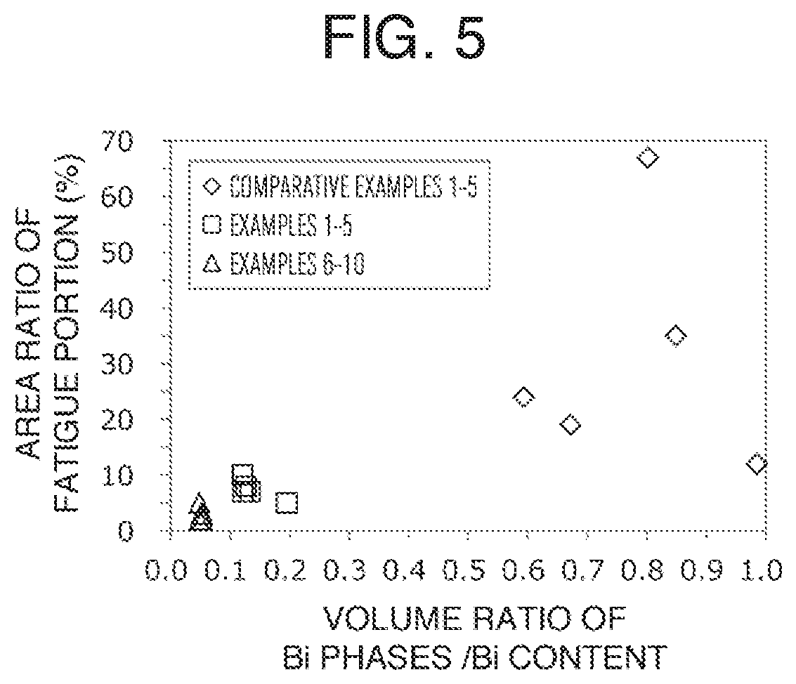
[0067]Samples of Examples 1 to 19 and Comparative Examples 1 to 5 below were produced, and a volume ratio of Bi phases in a region in the vicinity of the bonding interface and its influence on a fatigue property for each sample were evaluated.

Preparation of Substrate

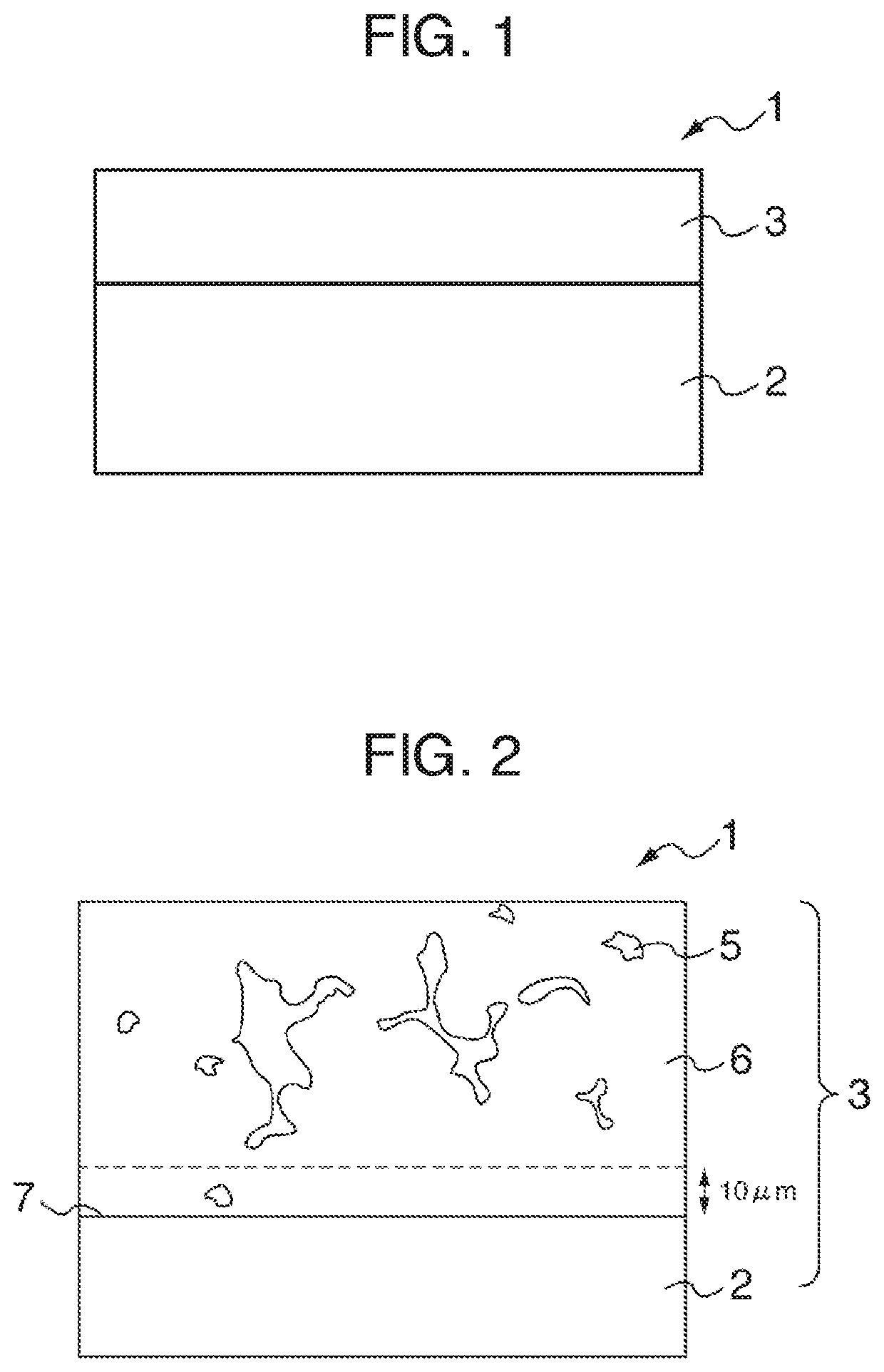
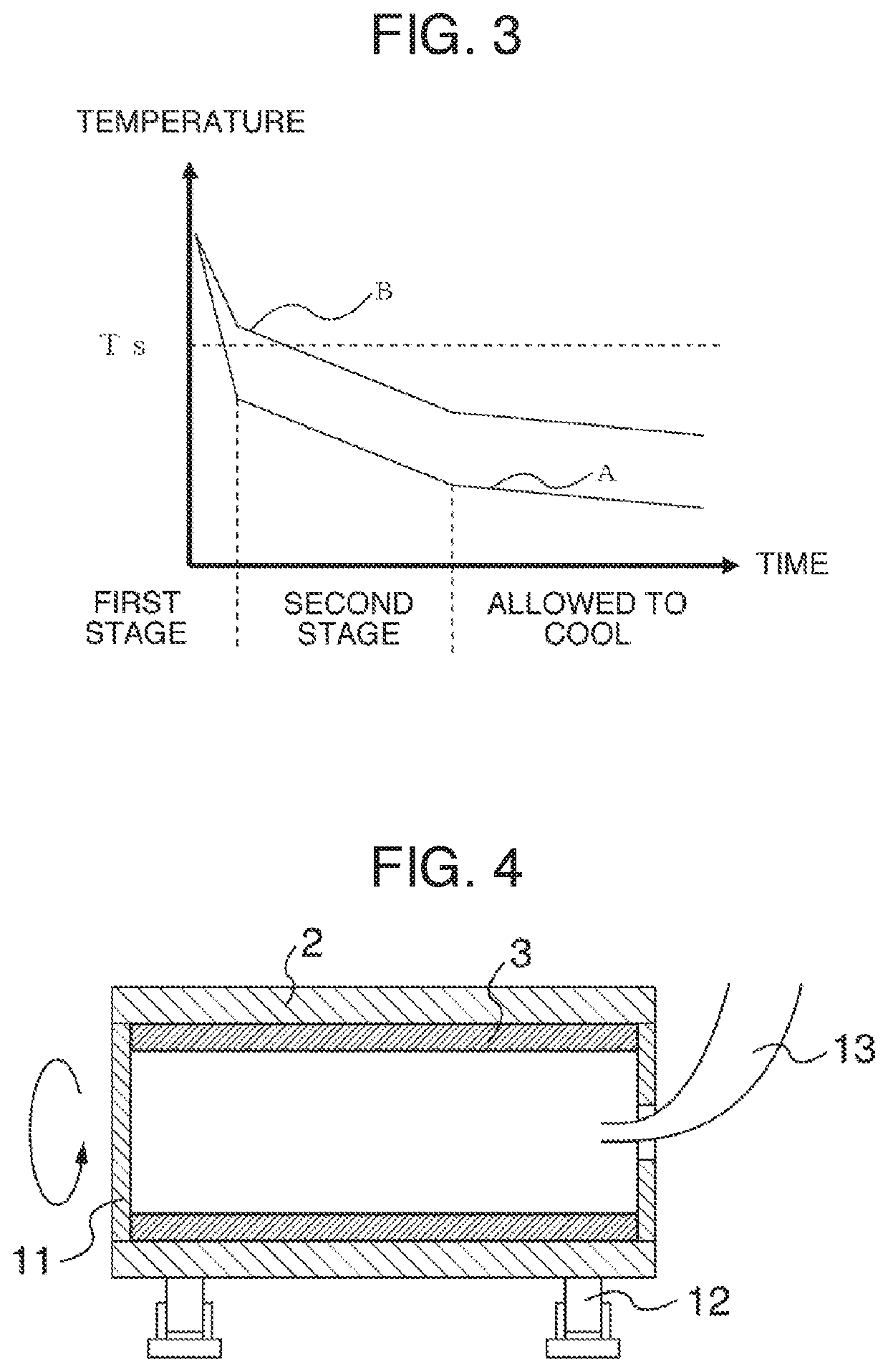
[0068]A SPCC steel plate was used as a substrate. A center portion of an upper surface of the steel plate was cut off while a periphery of the steel plate was left in order to prevent leakage of a molten alloy. Thus, the steel plate was processed into a box shape having a weir formed at the periphery. A casting thickness was set to 5 mm A portion to be a substrate of a sliding member had a thickness of 6 mm A surface of the substrate was covered with molten borax as an antioxidant, and the substrate was preheated at 1000° C. to 1200° C. in a reducing gas atmosphere including H2 gas.

Casting of Copper Alloy

[0069]As a copper alloy, materials including pure copper, pure Bi, and optionally other components were prepared so as...


PUM

PropertyMeasurementUnit
particle sizeaaaaaaaaaa
mass ratioaaaaaaaaaa
particle areaaaaaaaaaaa

Abstract

The purpose of the present invention is to provide: a slide member in which the bonding strength between a Bi-containing copper alloy layer and a substrate is enhanced; and a method for manufacturing the slide member. The slide member according to the present invention has a substrate and a copper alloy layer. The copper alloy layer comprises a copper alloy containing 4.0-25.0 mass % of Bi and has a structure in which Bi phases are scattered in a copper alloy structure. The volume ratio of Bi phases in the region of the copper alloy layer extending 10 μm from the bonding interface with the substrate is not more than 2.0%. The slide member is manufactured by casting a molten copper alloy onto the substrate and causing the copper alloy to unidirectionally solidify.

Description

TECHNICAL FIELD[0001]The present invention relates to a sliding member for an internal combustion engine, and specifically relates to a sliding member including a copper alloy layer on a substrate, the copper alloy layer having a structure including Bi phases dispersed in a copper alloy matrix. Furthermore, the present invention also relates to a method of manufacturing the sliding member.BACKGROUND ART[0002]A Cu—Sn—Pb-based sliding alloy has been used as a sliding material for a sliding bearing used for an internal combustion engine and various sliding members such as a bush or a thrust washer. However, in view of adverse effects of Pb on environment, a sintered copper alloy added with Bi, instead of Pb, has been proposed to achieve a Pb-free alloy. It has been known that Bi is dispersed in a Cu alloy matrix to form soft Bi phases to improve seizure resistance.[0003]For example, JP 2001-81523A (Patent Literature 1) discloses a copper-based sliding material including a Cu—Sn alloy i...

Claims


Application Information

Patent Timeline
Patent Type & Authority Applications(United States)
IPC IPC(8): F16C33/12C22C9/00B22D19/08F16C33/14
CPCC22C9/00F16C33/12B22D19/085F16C33/14B22D13/023B22D19/0009B22D19/16B22D27/04C22C1/02C22C9/02C22C9/04C22C9/05C22C9/06C22C9/10F16C33/06
Inventor TODA, KAZUAKI
Owner DAIDO METAL CO LTD
Why Eureka
Try Eureka