
Double-row matrix illumination module and auxiliary illumination method thereof

Active Publication Date: 2020-04-30
HASCO VISION TECHNOLOGY CO LTD
View PDF5 Cites 5 Cited by
  • Summary
  • Abstract
  • Description
  • Claims
  • Application Information

AI Technical Summary

Benefits of technology

The present invention provides a double-row matrix illumination module that can realize various functions such as conventional high beam, anti-dazzling high beam, low beam follow-up steering, and high beam follow-up steering. The high beam has multiple LED sources that can be turned on or off separately to illuminate different areas, which realizes the anti-dazzling high beam function. The follow-up steering function can be realized for both high beam and low beam, which improves the illumination experience when steering. The invention is compact, accurate in positioning, convenient for disassembly and assembly, and easy to guarantee the actual product quality.

Problems solved by technology

The existing matrix illumination modules cannot independently realize auxiliary light pattern design for low beam, high beam, left-bending and right-bending.
In addition, the existing matrix illumination modules are more complicated in mounting structure, imprecise in parts positioning, very difficult in positioning, inconvenient in disassembly and assembly and not conducive to ensuring the quality of the product.

Method used


Image

  • Double-row matrix illumination module and auxiliary illumination method thereof
  • Double-row matrix illumination module and auxiliary illumination method thereof
  • Double-row matrix illumination module and auxiliary illumination method thereof

Examples


Embodiment Construction

[0030]The present invention is further illustrated by the following drawings in combination with the embodiments.

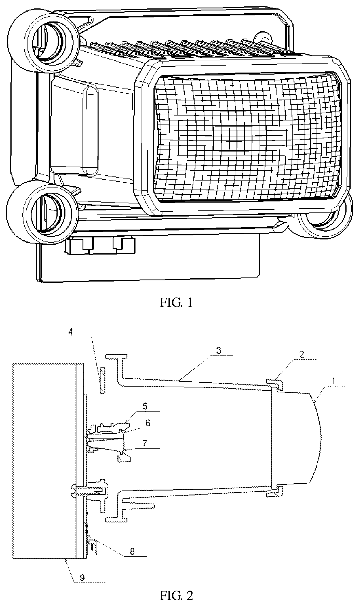
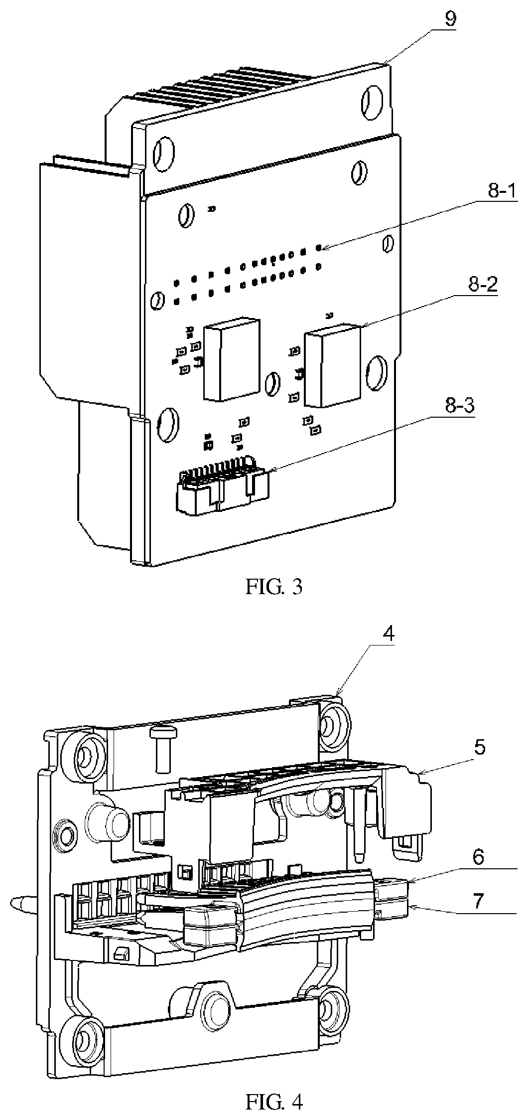
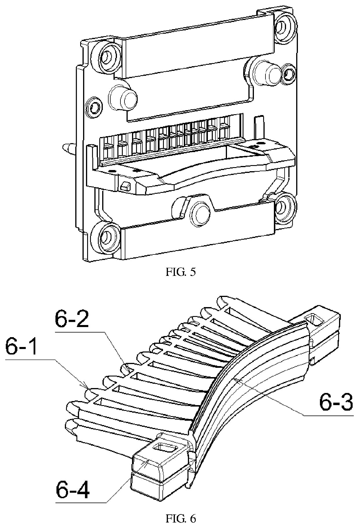
[0031]Referring to FIGS. 1-6, a double-row matrix illumination module comprises a light source part, a primary optical system and a secondary projection system; the light source part includes an LED circuit board 8 and a heat sink 9 that are secured to each other.

[0032]In the light source part, the LED circuit board is provided with dozens of LEDs in two rows; the LEDs are single-chip white light sources; the circuit board is a copper substrate and has good heat dissipation; the LED board comprises a control circuit module 8-2 for controlling turn-on or turn-off of LED chips and a connector assembly; the LEDs on the entire circuit board can be individually turned on or off and adjusted brightness; the heat sink is preferably made of aluminum profile, and has good heat dissipation effect, low processing cost and only need for cutting and drilling the aluminum profile.

[0033...


PUM


Abstract

The invention relates to a double-row matrix illumination module, wherein a light source part comprises an LED circuit board and a heat sink that are secured to each other; a primary optical system comprises a primary optical element mounting bracket, a primary optical element press plate and an LED circuit board. Primary optical elements are all mounted on the primary optical element mounting bracket in position. The primary optical elements are consisted of two layers, wherein the upper layer is primary optical element A and the lower layer is primary optical element B. The primary optical element mounting bracket configured as a base component for mounting and positioning comprises two rows of rectangular holes for fixing light-incident ends of the primary optical element A and the primary optical element B respectively and separating the light-incident ends from each other. The invention can realize anti-dazzling high beam function, low beam follow-up steering function, high beam follow-up steering; regarded as a whole, the follow-up steering function can be realized for the high beam and the low beam, thereby improving illumination experience when steering. Structurally, the invention is simple and compact, accurate in positioning, convenient for disassembly and assembly, easy to guarantee the actual product quality.

Description

BACKGROUND OF THE INVENTIONTechnical Field[0001]The invention relates to an illumination module, in particular to a double-row matrix illumination module and an auxiliary illumination method thereof.Description of Related Art[0002]As an updating product in automotive lighting technology, a matrix headlight attracts wide consumer. The matrix headlight adopting combination and arrangement of various light sources collects various driving status through an in-vehicle radar and sensor, then controls sub-light sources by an intelligent system, so that the light pattern can automatically adapt to the driving environment. At this time, the matrix headlight is not only an individual automotive part but also a terminal member in close fit with a ADAS system.[0003]The existing matrix illumination modules cannot independently realize auxiliary light pattern design for low beam, high beam, left-bending and right-bending. In addition, the existing matrix illumination modules are more complicated...

Claims


Application Information

Patent Timeline
IPC IPC(8): F21S41/153B60Q1/14
CPCF21S41/153B60Q1/1415F21S41/295F21S41/192F21S41/141F21S45/48F21V23/04F21Y2115/10F21W2107/10F21W2102/13F21S41/143F21S41/663F21W2102/14F21S41/19F21S41/24F21S41/255F21S41/29F21S41/322F21S41/20
Inventor ZHANG, DAPANSUN, XIAOFENQIU, ZHIPING
Owner HASCO VISION TECHNOLOGY CO LTD
Learn More