Neuromuscular Stimulation Using Multistage Current Driver Circuit

a driver circuit and multi-stage technology, applied in the direction of therapy, artificial respiration, pulse technique, etc., can solve the problems of common-mode latch-up issue, large power consumption, and difficulty in regulating output current, and achieve linear and accurate performance, less quiescent power, and high tolerance to resistance mismatch

Active Publication Date: 2020-05-21
BHAGAT NIKUNJ ARUNKUMAR +1
View PDF0 Cites 6 Cited by
  • Summary
  • Abstract
  • Description
  • Claims
  • Application Information

AI Technical Summary

Benefits of technology

[0013]To overcome abovementioned limitations, this disclosure presents a neuromuscular electrical stimulator (NMES) with a multistage driver circuit wherein, the multistage driver circuit comprises of a VCCS connected to an output driving stage with sourcing and sinking current mirror circuits. The multistage driver circuit enabled the NMES to generate high-voltage compliant constant current pulses, using low-cost components that operate at 95% less quiescent power, for electrically stimulating nerves and muscles. Additionally, to simultaneously stimulate multiple muscles, we disclose a stimulation method wherein a single multistage driver supplies current to first muscle, and the return lead from first muscle is used to drive current through another muscle or several other muscles. Further, using a network of switches and resistors, we can selectively divert or attenuate the current in the subsequent output drivers and thus, proportionally control the current intensities of multiple simultaneously stimulated multiples.
[0014]In the present embodiment, the VCCS generates an output current proportional to the input voltage. The output current is then transferred to a bidirectional current mirror circuit via a pair of unity-gain buffers comprising of folded-cascode bipolar transistors. The impedance matching providing by the unity-gain buffers, allows the VCCS and current mirror cir

Problems solved by technology

Conventional transistor-based current mirror circuits are susceptible to parameter variations and it is challenging to regulate their output current.
This requires a special-purpose, high-voltage rated operational amplifier (op-amp, e. g. PA341 DF from Cirrus Logic can operate up to 350V) which are expensive and consume large power.
While, the bootstrapped implementation is cheaper, it is susceptible to common-mode latch-up issue and hence, requires an op-amp with extremely wide common-mode input voltage range.
The prior art review, revealed two significant limitations in the present neuromuscular stimulation devices.
Firstly, the voltage-controlled current source (VCCS) design usi

Method used


Image

  • Neuromuscular Stimulation Using Multistage Current Driver Circuit
  • Neuromuscular Stimulation Using Multistage Current Driver Circuit
  • Neuromuscular Stimulation Using Multistage Current Driver Circuit

Examples


first embodiment

—FIGS. 1-4—FIRST EMBODIMENT

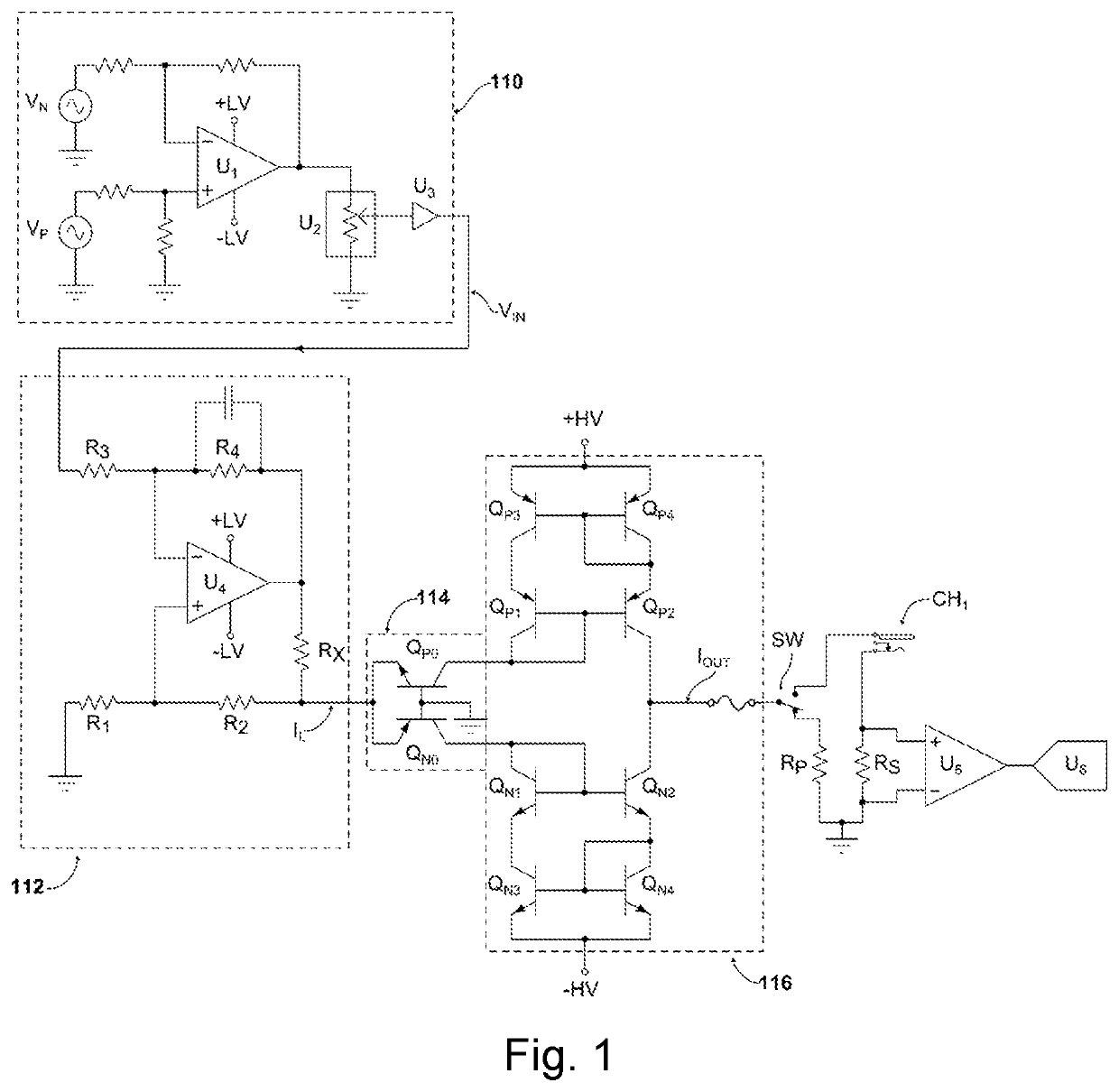
[0027]In one embodiment shown in FIG. 1, the neuromuscular stimulator consists of a waveform generator 110, a voltage controlled current source (VCCS) 112, and output driving circuitry 114 and 116. The waveform generator 110 consists of a pair of signal generators VP and VN that connect to an operational amplifier (op-amp) U1. The periods of VP and VN correspond to periods of the positive and negative phases of a biphasic stimulation waveform, respectively. In some embodiments, the periods and shape of VP and VN are generated by a microcontroller or by a digital-to-analog converter.

[0028]Op-amp U1 is configured as a difference amplifier with adjustable gain, to compute the difference between VP and VN. The amplitude of VP can also be scaled using the resistor divider network at the positive terminal of U1, such that VP is a fraction of VN. When VP is a fraction of VN, the period of VP is proportionally increased by the microcontroller, such that net charge...


PUM


Abstract

Neuromuscular stimulation is widely used for rehabilitation and movement assist devices, due to its safety, efficacy, and ease of operation. For repeatable and accurate muscular contractions, a voltage controlled current sources (VCCS) with high compliance is required. Conventional VCCS design requires high-voltage rated operational amplifiers, which are expensive and consume large power. Moreover, conventional stimulators are not viable for simultaneous stimulation of muscle synergies, as they require multiple VCCS operating at the same time. This invention presents a neuromuscular stimulator with a multistage driver circuit wherein, a VCCS connected to an output driving stage comprising of folded-cascode transistor buffers and a bidirectional current mirror circuit. The multistage driver circuit uses inexpensive low-voltage rated operational amplifiers that consume 95% less power. Additionally, we disclose a stimulation method wherein only a single current source drives several output drivers connected in series or parallel to simultaneously stimulate multiple muscles or muscle synergies.

Description

CROSS-REFERENCE TO RELATED APPLICATIONS[0001]This application claims the benefit of provisional patent application Ser. No. 62 / 589,237, filed 2017 Nov. 21 by the present inventors, which is incorporated by reference in its entirety.REFERENCES CITEDU.S. Patents[0002]5,562,718June 1994Palermo607 / 465,514,165May 1996Malaugh, et al607 / 466,762,646 B1July 2004Bell330 / 257U.S. Patent Application Publications[0003]20170281941A1October 2017Page et alA61N 1 / 36021Non-patent Literature Documents[0004]1) Wen-Whe, et al., (1998) A high DC-gain folded-cascode CMOS operational amplifier. In Proceedings of IEEE Southeastcon '98 ‘Engineering for a New Era’, Orlando, Fla., USA, 1998, pp. 176-177.[0005]2) Wu, et al., (2002). A versatile multichannel direct-synthesized electrical stimulator for FES applications. IEEE Transactions on Instrumentation and Measurement, 51(1), 2-9.[0006]3) Caldwell, (2013). A high-voltage bidirectional current source. Texas Instruments, technical note.[0007]4) Shendkar, et al....

Claims


Application Information

Patent Timeline
IPC IPC(8): A61N1/36H03K3/26A61N1/02A61N1/04
CPCH03K3/26A61N1/3603A61N1/0452A61N1/025A61N1/0456A61N1/36003A61N1/36034H03K4/94H03K5/02H03K5/13
Inventor BHAGAT, NIKUNJ ARUNKUMARCONTRERAS-VIDAL, JOSE LUIS
Owner BHAGAT NIKUNJ ARUNKUMAR
Why Eureka
Try Eureka