
Milling tool device for auxiliary chip breaking and tool system for auxiliary chip breaking under different lubricating conditions

a technology of auxiliary chip and tool device, which is applied in the field of machining, can solve the problems of reducing affecting the quality of the finished product, so as to improve the processing quality and tool life, reduce the damage of the longer chip, and expand the application scope of the whole tool devi

Inactive Publication Date: 2020-05-28
QINGDAO TECHNOLOGICAL UNIVERSITY +2
View PDF0 Cites 3 Cited by
  • Summary
  • Abstract
  • Description
  • Claims
  • Application Information

AI Technical Summary

Benefits of technology

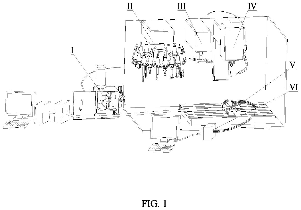
The present invention is a tool device that helps to break chips. It uses a cutting mechanism to mill the workpiece. There is also a mechanism that can hold and select different tools. This invention aims to overcome the deficiencies of previous designs that made chip breaking difficult.

Problems solved by technology

However, during milling, the time that a tool comes into contact with a workpiece is very short; a sever friction occurs between a rake face of the, tool and chips and between a flank face and the workpiece, which generates a lot of cutting heat, causing the sharp wear of the tool, and consequently, the tool fails fast, thereby seriously restricting the improvement of machining efficiency.
When brittle materials are machined, brittle fracture occurs in the metal on a cutting layer without plastic deformation, thereby generating crack ships with irregular shapes, causing an uneven machining surface.
Therefore, in the case that the cutting conditions and cutting parameters are changed, the chip shape may change, and meanwhile, the problem of no chip breaking or excessive chip breaking often occurs, and unbroken disorderly chips scrap the machined surface, causing the fault of a machine tool spindle, and even causing the production safety problems and low production efficiency.

Method used


Image

  • Milling tool device for auxiliary chip breaking and tool system for auxiliary chip breaking under different lubricating conditions
  • Milling tool device for auxiliary chip breaking and tool system for auxiliary chip breaking under different lubricating conditions
  • Milling tool device for auxiliary chip breaking and tool system for auxiliary chip breaking under different lubricating conditions

Examples


Embodiment Construction

[0078]It should be pointed out that, the following detailed description is exemplary and aims at providing further description to the present application. All technical and scientific terms used herein have the same meanings as those usually understood by those ordinary skilled in the art of the present application, unless otherwise specified.

[0079]It should be noted that, the terms used herein are only used for describing specific implementation, not intended to limit the exemplary implementation according to the present application. As used herein, a singular form is also intended to include a plural form, unless otherwise clearly specified in the context. In addition, it should be understood that, when the terms “contain” and / or “include” are / is used in the description, it specifies the existence of features, steps, operation, devices, components and / or their combinations.

[0080]As introduced in the background of the present invention, in view of the deficiencies in the prior art,...


PUM


Abstract

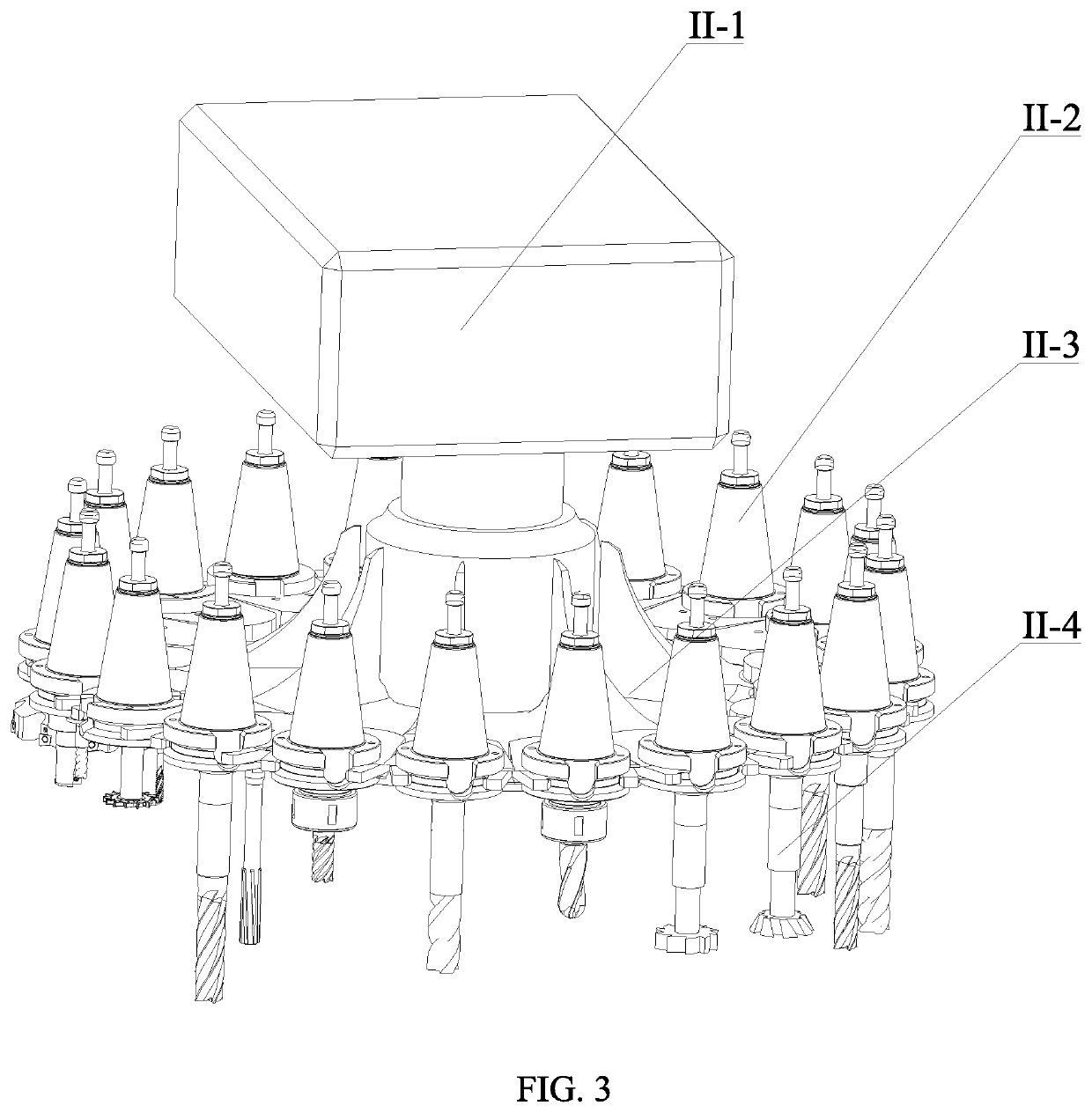
The present invention discloses a tool device for auxiliary chip breaking and a tool system for auxiliary chip breaking under different lubricating conditions, which solves the problem that long chips affect the surface quality of a workpiece in the prior art and has the beneficial effects of realizing chip breaking and wide scope of application. The solution of the present invention is as follows: the tool device for auxiliary chip breaking includes a cutting mechanism for cutting the workpiece, arranged above the workpiece; a tool magazine mechanism, including a first rotating mechanism and a plurality of tools connected with the first rotating mechanism; and a tool changing mechanism, including a second rotating mechanism and manipulators connected with the second rotating mechanism, and arranged between the tool magazine mechanism and the cutting mechanism.

Description

CROSS-REFERENCE TO RELATED APPLICATIONS[0001]This application claims priority to Chinese Patent Application No. 201811399655.5 with a filing date of Nov. 22, 2018. The content of the aforementioned applications, including any intervening amendments thereto, are incorporated herein by reference.TECHNICAL FIELD[0002]The present invention relates to the field of machining, and particularly relates to a tool device for auxiliary chip breaking and a tool system for auxiliary chip breaking under different lubricating conditions.BACKGROUND OF THE PRESENT INVENTION[0003]Currently, milling machining is cutting machining which is the most commonly used in the mechanical manufacturing industry, and has high machining production efficiency, wide machining range and high machining precision. However, during milling, the time that a tool comes into contact with a workpiece is very short; a sever friction occurs between a rake face of the, tool and chips and between a flank face and the workpiece,...

Claims


Application Information

Patent Timeline
Patent Type & Authority Applications(United States)
IPC IPC(8): B23Q11/10B23C1/06B23Q3/157B23Q3/155
CPCB23Q2003/155418B23Q11/10B23Q2003/155446B23Q3/1554B23Q3/15722B23Q2003/155428B23C2250/12B23C1/06B23Q3/15713B23Q11/1046B23Q17/09B23C5/10B23C2210/483
Inventor LI, CHANGHEYIN, QINGANCAO, HUAJUNDING, WENFENGZHANG, NAIQINGLIU, YONGHONGBAI, XIUFANGDONG, LANDUAN, ZHENJINGZHANG, YANBINSUI, MENGHUAWU, WENTAOGAO, TENGYANG, MINJIA, DONGZHOULI, RUNZEHOU, YALI
Owner QINGDAO TECHNOLOGICAL UNIVERSITY
Learn More