
Digital stereo multiplexing-demultiplexing system based on linear processing of a Delta - Sigma modulated bit-stream

Inactive Publication Date: 2020-06-04
ZRILIC DJURO GEORGE
View PDF4 Cites 0 Cited by
  • Summary
  • Abstract
  • Description
  • Claims
  • Application Information

AI Technical Summary

Benefits of technology

This patent introduces a new system for digitally mixing and separating two stereo signals. The system uses a high-resolution Δ-################ modulator and four binary delta adders. The system can operate at different frequencies and can be used for long-distance transmission. It can handle audio, photo, and video signals and can perform addition and subtraction on a second-order Δ-rupmodulated bit-stream. Overall, the patent introduces a new and flexible method for digitally mixing and separating stereo signals.

Problems solved by technology

Unfortunately, it requires several external analog components to make it operate (including two inductor (coil) components).
Thus, FM IC chips have to be buffered by a number of analog components which is not possible to integrate.
1. Tatsuta et al discloses a wireless transmission system for wirelessly connecting signal source apparatus and signal sink apparatus (U.S. patent application Ser. No. 12 / 0888,832). From the proposed apparatus in FIG. 1, it is possible to see that a signal source is a DVD player, and a signal sink is a PDP apparatus. In FIG. 2 and in FIG. 3, a block diagrams are marked, but without any explanation how they operate, or how they are implemented. From the description and from the block diagrams it is not possible to resolve what kind of digital modulation technique is used for digital multiplexing: pulse code modulation (PCM), differential code modulation (DPCM), delta-sigma modulation (DSM) etc. Thus, from the description and from the block diagram, it is not possible to resolve how many bits per sample of video or audio signal is used (8-bit PCM, 16-bit PCM, etc.). From claims 19 to 34 it is possible to conclude that 2 channel wireless apparatus is proposed without mentioning delta-sigma modulation (DSM), arithmetic operations on delta-modulated bit-stream, or delta-sigma based stereo technique.
2. Kamiya disclosed mixing, coding and decoding devices and methods which the operation is based on mixed use of delta-sigma and pulse code modulation (U.S. patent application Ser. No. 08 / 864,552). From the proposed FIG. 1 one can see enormous complexity of the proposed digital signal processing circuitry. To avoid conversion of the data into analog domain, Kamiya proposes to mix 16-bit PCM signal and one-bit DSM bit-stream. However, this approach has some disadvantages.
First, the decimation technique is silicon area consuming (complex) and expensive.
Second, weighted 16-bit multipliers are bulky and slow (usually multiplication is done on the shift-and-add principle).
Third, PCM adder (No. 13, in FIG. 1) is very complex. It adds four 16-bit PCM words and produces 17-bit word.
Fourth, delta-sigma modulator (13), introduces additional quantization noise. It is important to mention that every one of those elements introduce additional noise into proposed system shown in FIG. 1. One can conclude, that the price and complexity of mixed “full-digital processing” (to avoid conversion of data into analog domain) is too big. Having a 16-bit word, one can expect the problem of reliability, because the most frequent malfunction happens at connection of metal wire and semiconductor (16 parallel wires / word)! Even though delta-sigma modulator is used as the ADC of the analog signal, entire DSP processing is done with 16-bit PCM code word, and at the output again converted into serial bit-stream using delta-sigma modulator.
3. Algazi et al proposed a new approach for tracking a head motion of headphone-based sound (U.S. patent application Ser. No. 11 / 845,607). In FIG. 1, of this invention, the basic concept of the invention is presented. It consists of microphone array, signal processing unit, and head tracker. From existing block diagrams and flow charts, it is impossible to conclude what kind of signal processor is employed. One cannot find data about the analog-to-digital convertor used and its resolution (a number of bits per sample), or any implementation solution. Without implementation schematics, measurement, or simulation results it is very difficult to judge the validity of the general concept proposed, or contrast and compare it with the existing solutions.
4. McArthur et al presented a wireless digital audio system which includes a transmitter that performs parallel acquisition of audio data from plural audio data. A set of Codecs convert the incoming multi-channel analog signal to serial digital bit stream. If a digital audio input signal is used, the Codecs can be bypassed. FIG. 3 of this invention (U.S. patent application Ser. No. 11 / 499,126) clearly presents radio transmitter including a timing marker for the packetization of parallel collected data. RF packet data stream is transmitted to the receiver (shown in FIG. 4 of this invention) which includes a timer unit responsive to receive a timing marker and a clock for synchronization and demultiplexing. In FIG. 5A and FIG. 5B one can see the complexity of the proposed wireless radio system. In addition to standard blocks, the transmitter consists of forward error correction block (FEC) and packet buffer block. The receiver has additional blocks for processing redundant and prior data. From block diagrams and from description it is not possible to conclude what kind of CODEC is used (PCM or Δ-Σ). In addition, direct processing of Δ-Σ bit stream is not mentioned at all.
It will be very difficult, if not impossible, to combine the techniques of Tatsuta, Kamaya, Algazi, McArthur, to obtain system proposed in this application.

Method used


Image

  • Digital stereo multiplexing-demultiplexing system based on linear processing of a Delta - Sigma modulated bit-stream
  • Digital stereo multiplexing-demultiplexing system based on linear processing of a Delta - Sigma modulated bit-stream
  • Digital stereo multiplexing-demultiplexing system based on linear processing of a Delta - Sigma modulated bit-stream

Examples


Embodiment Construction

Definition

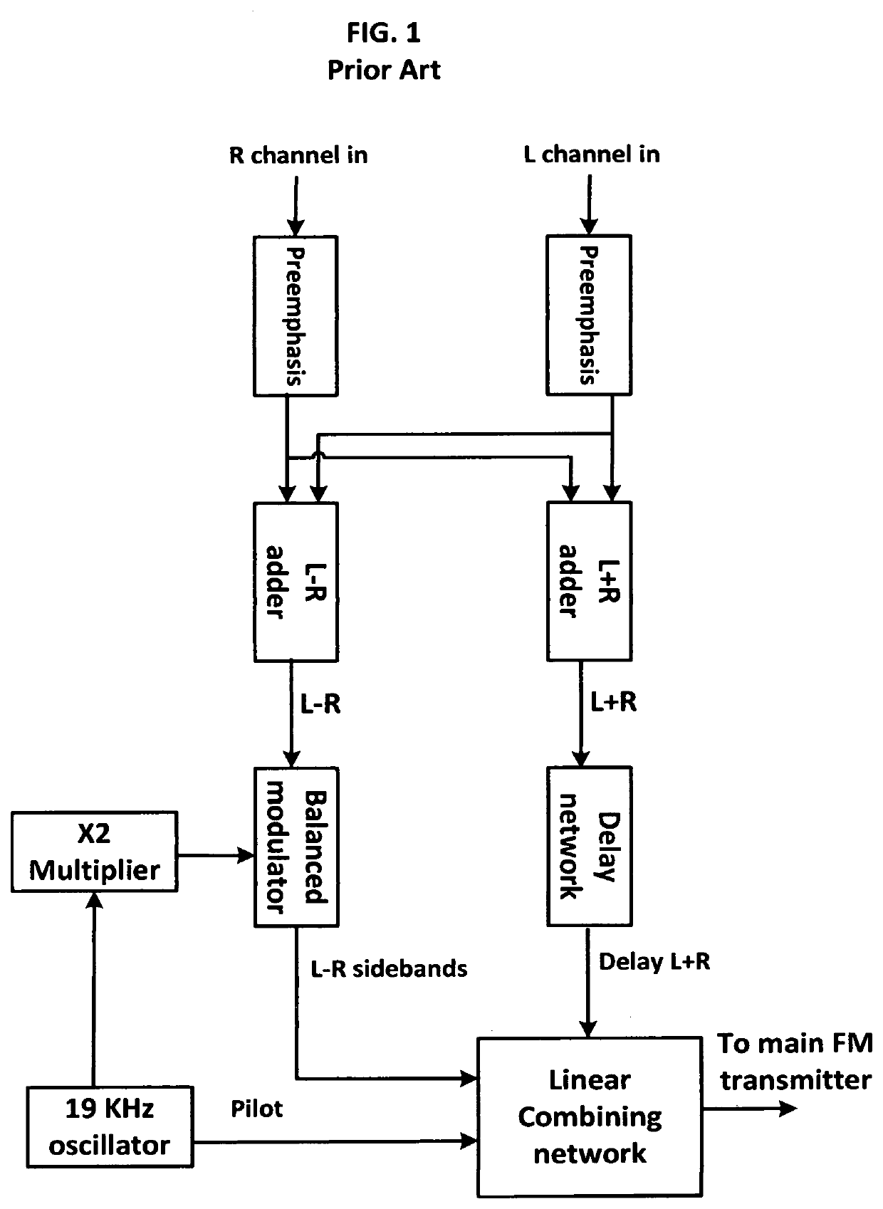
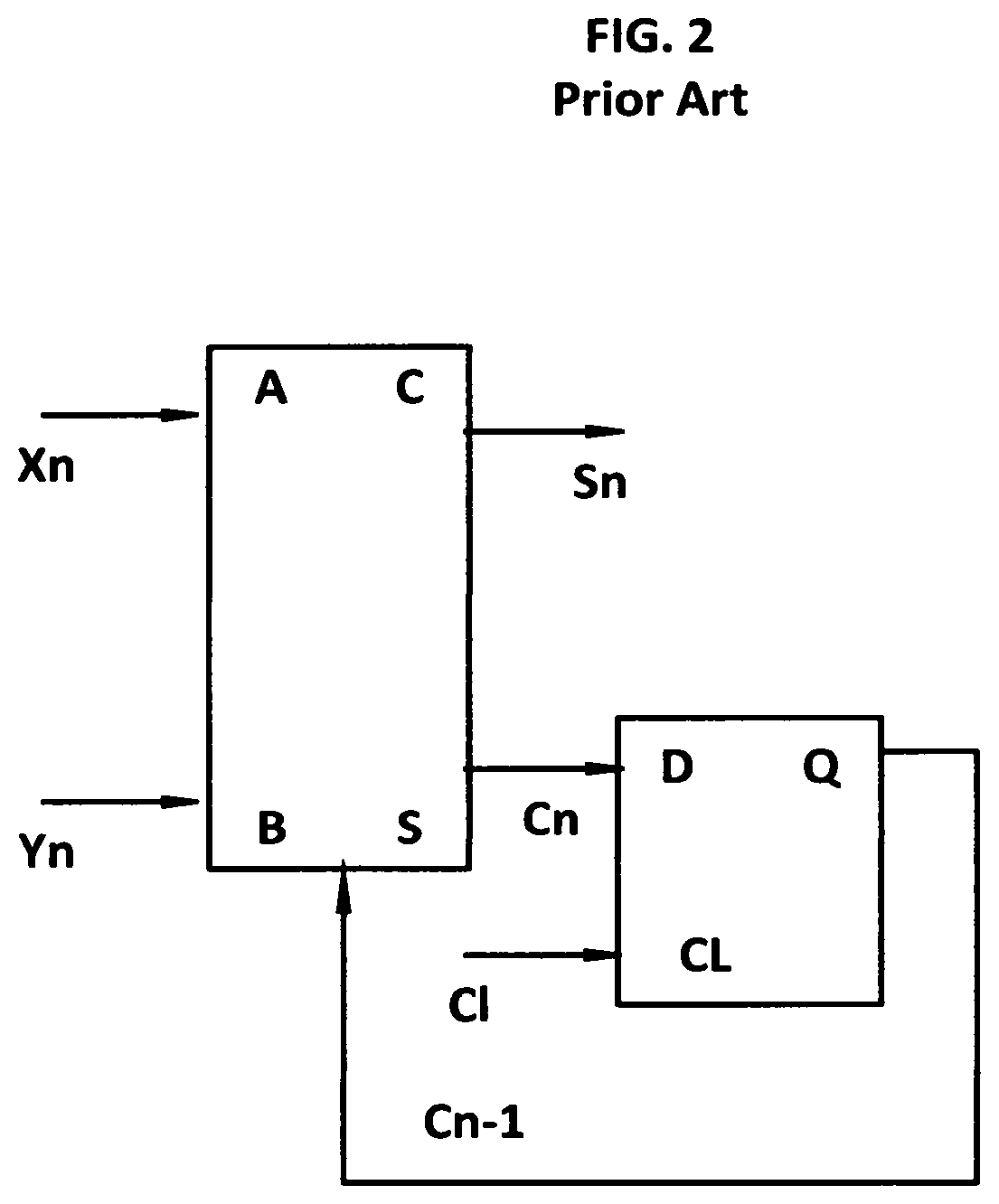
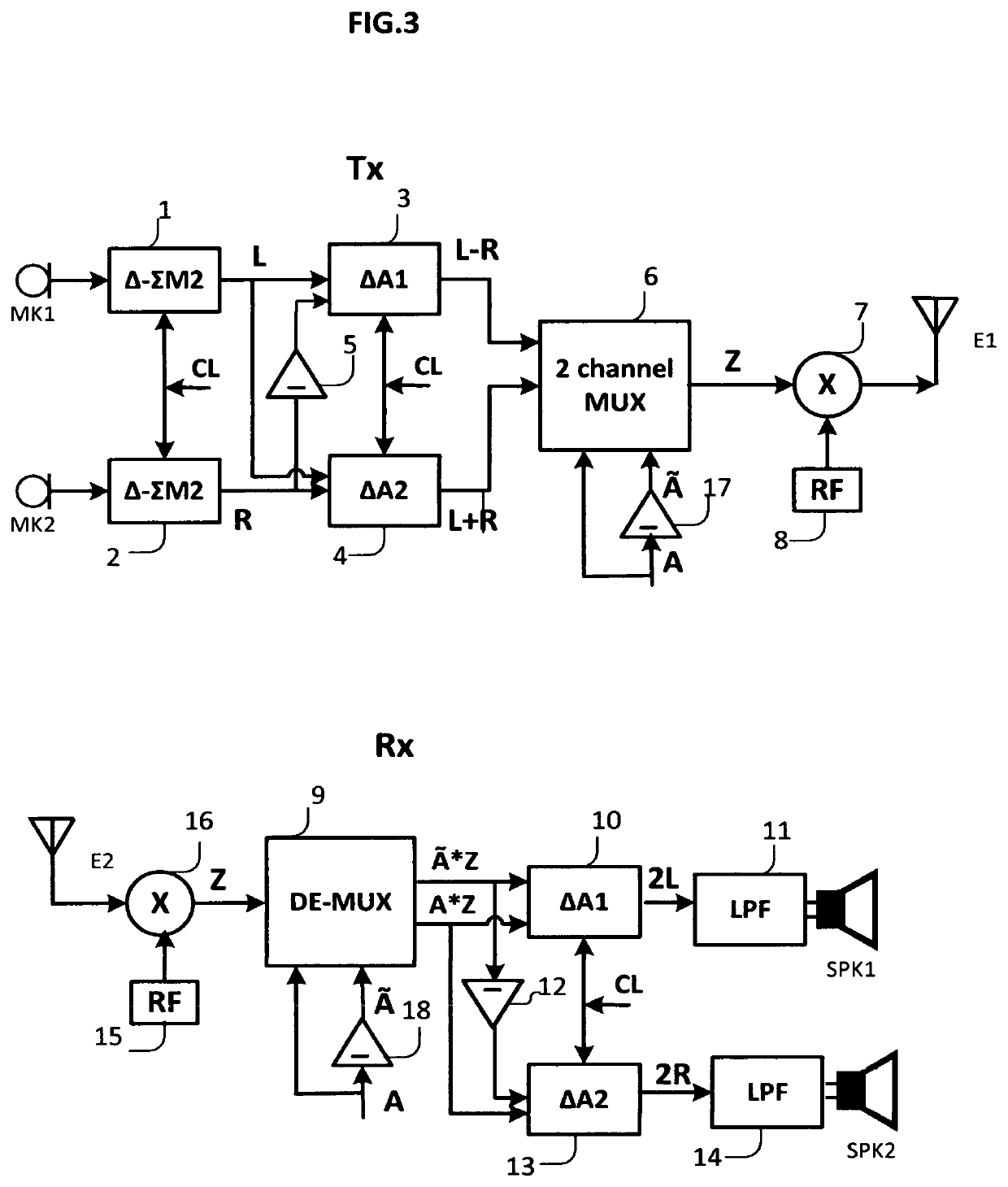
[0038]A stereo multiplexing-demultiplexing system is the main component of any stereo transmission system. Most existing stereo techniques are based on a frequency multiplexing technique. The proposed method of this invention consists of a high resolution Δ-Σ modulator whose resolution is greater than 20 bits. In addition to the simple and inexpensive high-resolution Δ-Σ modulator implementation [3], [4], it is possible to perform linear arithmetic operations of addition, subtraction, and multiplication by a constant less than 1 on its bit-stream. To implement addition / subtraction of the left (L) and right (R) channels a special circuit must be developed. An ordinary serial binary adder, with interchanged role of the terminals of Carry-Out and Sum, can perform addition / subtraction of two Δ-Σ modulated bit-streams [2]. Thus, the main contribution of this invention is a simple, inexpensive and reliable digital stereo multiplexing-demultiplexing system, based on a direct arit...


PUM


Abstract

Disclosed is a digital stereo multiplexing-demultiplexing system based on the use of delta-sigma modulation. Creation of left (L−R) and right (L+R) channels is achieved using a binary delta adder IC circuit. Delta adder is an ordinary binary adder with an interchanged role of the Sum and Carry-Out terminals. Two channel multiplexer and demultiplexer are implemented with ordinary binary logic gates. Output of the multiplexer is modulated and transmitted to the receiver where demultiplexing is performed. The proposed method can combine two or more digital stereo channels. This method is not application limited, and can be used in acoustic, video, or photo applications.

Description

CROSS REFERENCES TO RELATED APPLICATIONS[0001]Fields, Craig D., U.S. Pat. No. 5,274,708, Date of patent: Dec. 28, 1993[0002]Edgar, Albert D., U.S. Pat. No. 5,278,909, Date of patent: Jan. 11, 1994[0003]Wildhagen, Jens, U.S. Pat. No. 7,092,460, Date of patent: Aug. 15, 2006[0004]Newbery, Billy, U.S. Pat. No. 8,982,181, Date of patent: Mar. 17, 2015[0005]Amadu, Frederic; Esnault, Thomas, U.S. Pat. No. 9,111,529, Date of patent: Aug. 18, 2015[0006]Kamiya, Ryo, U.S. Pat. No. 6,438,434, Date of patent: Aug. 20, 2002[0007]McArtur, Kelly; Hudson, Michael, US Patent No. 2007 / 0030986 A1, Date of patent: Feb. 8, 2007[0008]Algazi, Ralph; Duda, Richard; Thompson, Dennis, US Patent No. 2008 / 0056517 A1, Date of patent: Mar. 6, 2008[0009]Tatsuta, Akihiro; Nishikawa, Yoshikane; Funabiki, Makoto; Ohue, Hiroshi, US Patent No. 2009 / 0260043 A1, Date of patent: Oct. 15, 2009STATEMENT REGARDING FEDERALLY SPONSORED R&D[0010]These research results are not sponsored by Government grants.NAME OF PARTIES TO A...

Claims


Application Information

Patent Timeline
IPC IPC(8): H04B1/16H03M7/32
CPCH04B1/1676H03M7/3017H04B1/1692H03M3/468H04B1/0028H04B1/1646
Inventor ZRILIC, DJURO GEORGE
Owner ZRILIC DJURO GEORGE
Learn More