
Distributed fibre sensing system and vibration detection and positioning method therefor

a distributed fibre and vibration sensing technology, applied in the field of fibre sensing, can solve the problems of limited application of such distributed fibre vibration sensing systems, low power of optical probe pulses, and incongruity of vibration frequency response bandwidth and sensing distance of systems, and achieve long detection distance, increase the effect of vibration frequency response bandwidth and spatial resolution

Active Publication Date: 2020-06-11
SHANGHAI JIAO TONG UNIV +1
View PDF0 Cites 13 Cited by
  • Summary
  • Abstract
  • Description
  • Claims
  • Application Information

AI Technical Summary

Benefits of technology

This patent invention has several technical effects. It can create high quality images with precise detection and positioning of vibration points. It can also expand the frequency response bandwidth and eliminate distortion caused by weak reflection points. Overall, it improves the overall signal-to-noise ratio and accuracy of vibration detection and positioning.

Problems solved by technology

However, there are two major defects: first, the vibration frequency response bandwidth and the sensing distance of the system are contradictory.
This defect severely limits the application of such distributed fibre vibration sensing system in the field of high-frequency vibration sensing.
To achieve a high spatial resolution, the duration of opticas probe pulse must be very short, which results in a very low power of the optical probe pulse, and in turn limits toe detection range.
With respect to the contradiction between the vibration frequency response bandwidth and the sensing distance, there are currently several solutions as follows: a distributed fibre vibration sensing system based or an optical frequency-domain reflectometer, which can obtain frequency information of high frequency vibration, but cannot obtain time domain information of the vibration; a distributed fibre sensing system based on an interferometer, which can obtain a very large range of vibration frequency response, but has disadvantages of complicated demodulation algorithm and poor positioning accuracy; a distributed fibre sensing system based on a fusion structure of an interferometer and an optical time-domain reflectometer, which has obtained advantages of the two kinds of systems described above, but becomes complicated and requires the sensing fibre to be of a ring structure, resulting in a failure of single-end measurement; and a distributed sensing system based on a frequency-division multiplexing technology and an optical time-domain reflectometer, whose overall performances, such as spatial resolution, measurable range and signal-to-noise ratio, still need to be improved.

Method used


Image

  • Distributed fibre sensing system and vibration detection and positioning method therefor
  • Distributed fibre sensing system and vibration detection and positioning method therefor
  • Distributed fibre sensing system and vibration detection and positioning method therefor

Examples


embodiment 1

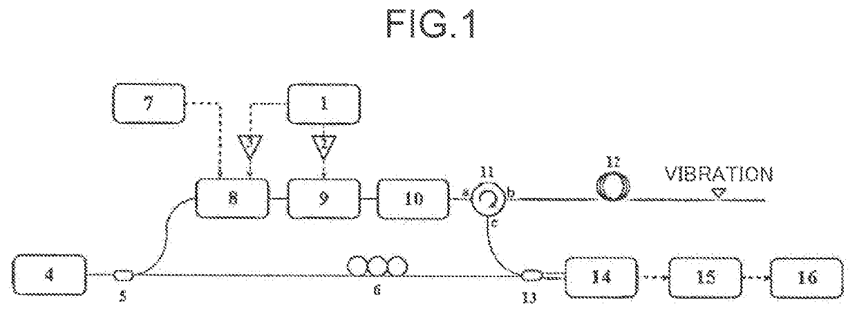
[0034]As shown in FIG. 1, the present embodiment comprises: a signal generating module, a light source module, an optical frequency comb generating module, a frequency sweeping and pulse generating module, an optical circulator 11, a sensing fibre 12, an interference module, a photoelectric conversion module and a detection and position module, wherein: the signal generating module inputs an amplified swept radio frequency pulse sequence and an amplified single-frequency sinusoidal wave signal to the frequency sweeping and pulse generating module and the optical frequency comb generating module respectively, and the signal generating module sends a trigger signal to the detection and position module at the same time; an ultra-narrow-linewidth laser generated by the light source module is split into a detection light path and a reference light path which are then output to the optical frequency comb generating module and the interference module, respectively; the optical frequency co...


PUM


Abstract

A distributed fibre sensing system and a vibration detection and positioning method therefor are disclosed. The system comprises: a signal generating module, a light source module, an optical frequency comb generating module, a frequency sweeping and pulse generating module, an optical circulator, a sensing fibre, an interference module, a photoelectric conversion module and a detection and position module. The method comprises: obtaining a plurality of Rayleigh backscattering signals of the sensing fibre; performing a fading elimination processing on the Rayleigh backscattering signals, thereby obtaining a plurality of averaged Rayleigh backscattering signals of non-interference fading and polarization fading; performing a phase processing on the averaged Rayleigh backscattering signals, thereby obtaining phase variance curves; and determining a vibration point according to variances in the phase variance curves, and finally obtaining a position and a vibration waveform of the vibration point.

Description

TECHNICAL FIELD[0001]The present invention relates to a technology in the field of fibre sensing, in particular, to a distributed fibre sensing system and a vibration detection find positioning method therefor.BACKGROUND ART[0002]Since the invention of optical fibre in the 1970s, the fibre sensing technology has also been booming. In addition to being used for long-range high-speed communications, the fibre also has an ability to sense external physical parameters. By means of this sensitive characteristic, researchers invented a series of fibre sensing devices among which the distributed fibre vibration sensor has been a research hotspot in recent years. Compared with traditional vibration sensors, the distributed fibre vibration sensor has many advantages, such as water and moisture resistance, anti-electromagnetic interference and use safety, and most importantly, has distributed sensing and long-distance sensing capabilities.[0003]At present, toe most widely used and most studie...

Claims


Application Information

Patent Timeline
Patent Type & Authority Applications(United States)
IPC IPC(8): G01H9/00G01D5/353
CPCG01D5/35358G01H9/004G01D5/35306
Inventor HE, ZUYUANLIU, QINGWENCHEN, DIANFAN, XINYU
Owner SHANGHAI JIAO TONG UNIV
Learn More