
Eureka
For R&D, Eureka makes reading and utilizing patents & technical documents easy.
Eureka AIR
Designed for self-driven R&D workflows. Generate viable solutions, solve complex R&D challenges, empower your innovation with AI.

Eureka Materials
Designed for material experts only. Revolutionize your material R&D, from search, analyze, to developing new materials.

TechResearch
Generate reliable direction feasibility study reports for your R&D in just a few steps.

TechSeek
Discover and master advanced knowledge NOW. Basics, ideas, possibilities, all at once.

TechMind
As an expert in R&D Theories, TechMind can generates customized viable solutions instantly.

TechRisk
Analyze your overall solution with one click, know your potential R&D risks in advance.

TechMonitor
Get weekly tech updates, stay abreast of the latest tech innovations and key insights.
Display device and display method
- Summary
- Abstract
- Description
- Claims
- Application Information
AI Technical Summary
Benefits of technology
Problems solved by technology
Method used
Image

Examples
first embodiment
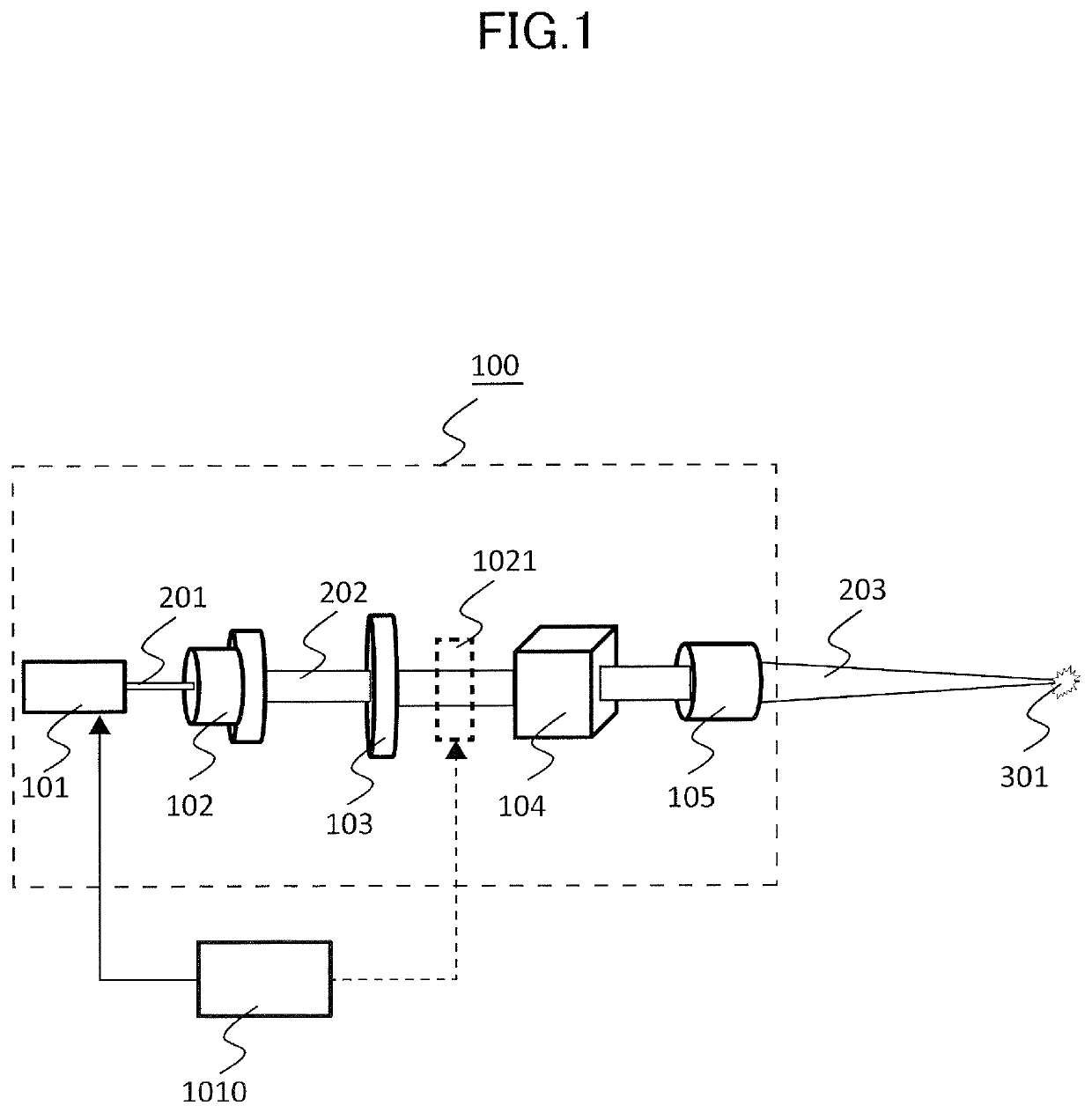
Laser Irradiation Device
[0035]The display device (image forming device) of the present embodiment uses a laser beam in a predetermined wavelength range, especially, in a wavelength range of visible light; and allows observers to visually identify an emission color of the laser beam. Here, the predetermined wavelength range or the wavelength range of visible light may vary depending on the definition and the individual difference in observers. Thus, in the present embodiment, the wavelength range of visible light is defined as a range equal to or larger than 380 nm and equal to or smaller than 780 nm. However, even when a later-described value varies in a range from zero to tens of nanometers in the predetermined wavelength range (wavelength range of visible light), substantially the same effect will be produced by achieving the same configuration or control as that of a later-described example. The present embodiment differs from the conventional techniques, which uses an invisible ...
example 1
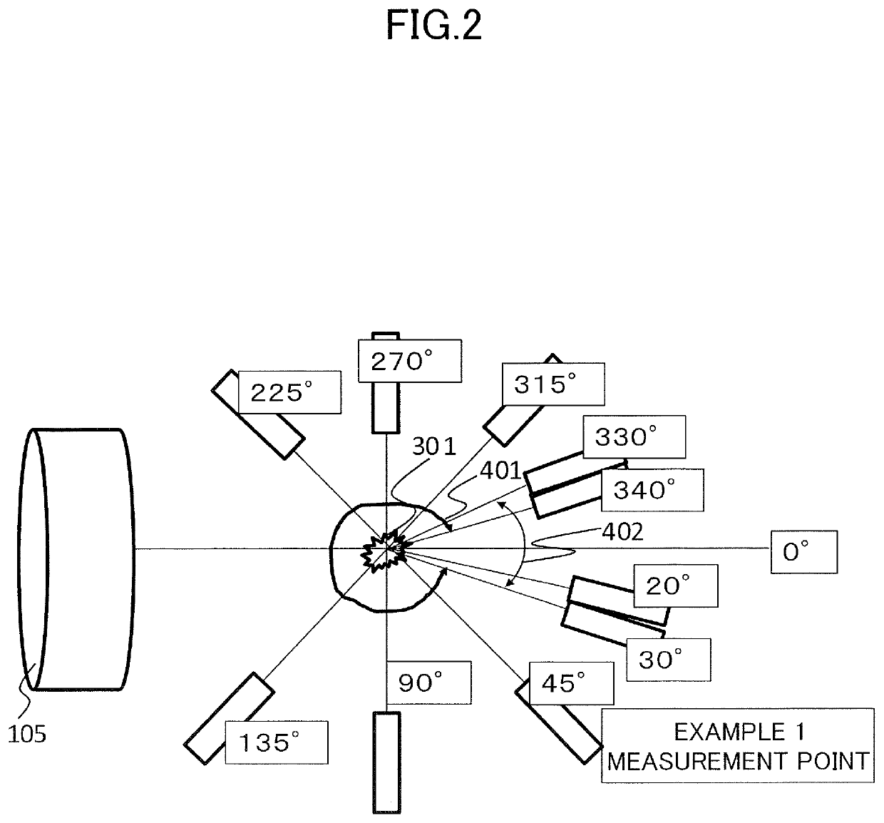
[0098]In this example, other spectral curves were measured at an angle of 45° while the laser power of the green laser-light source L1 was changed. In addition, a spectral curve was measured at angles illustrated in FIG. 2. Specifically, the laser beam was emitted, and the energy at the focal point was changed by adjusting the polarizing plate and the beam splitter. In this time, the Y value of the light emitter in a range from 522 to 542 nm and the Y value of the plasma light were compared (the measurement position of the light emitter was 45°, and the distance of the light emitter was 50 mm). The laser power was 1500 mW.
[0099]The light emitter was able to be identified as a green light emitter in an angle range from 30° to 330°. FIG. 15 illustrates XYZ values of the light emitter calculated from xy values of the light emitter (the XYZ values include values of the scattered laser beam and values of the plasma light). As illustrated in FIG. 15, emission colors identified are all in ...
example 2
[0103]The conditions of Example 2 are the same as those of Example 1 except that the above-described blue laser-light source L2 was used. Specifically, the laser beam was emitted from the laser light source L2, and the energy at the focal point was changed by adjusting the polarizing plate and the beam splitter so that the ratio of the Y value of the plasma light from the light emitter to the Y value of the scattered laser beam at or near the dominant wavelength of the laser beam was 95% or less. As a result, a blue light emitter was visually identified in the observation angle from 30° to 330° of FIG. 2. FIG. 16 illustrates xy values of the light emitter located at the display position. The xy values were calculated from XYZ values. As illustrated in FIG. 16, emission colors identified were all in the blue-color range (in the blue-color range, x is in a range from 0.16 to 0.30 and y is in a range from 0 to 0.30).
[0104]At an observation angle of 20°, a blue-green color that is a mix...
PUM
 Abstract
Description
Claims
Application Information
 - R&D Engineer
- R&D Manager
- IP Professional
- Industry Leading Data Capabilities
- Powerful AI technology
- Patent DNA Extraction
Browse by: Latest US Patents, China's latest patents, Technical Efficacy Thesaurus, Application Domain, Technology Topic, Popular Technical Reports.
© 2024 PatSnap. All rights reserved.Legal|Privacy policy|Modern Slavery Act Transparency Statement|Sitemap|About US| Contact US: help@patsnap.com