
Transillumination imaging instrumentation with scattered light discrimination

a technology of scattered light and imaging instrument, applied in the field of transillumination imaging instrument, can solve the problems of missing an anomaly altogether, difficult to detect small structures in an object being imaged, and thickness contour of the subject obj

Inactive Publication Date: 2001-06-05
WIST ABUND OTTOKAR
View PDF8 Cites 129 Cited by
  • Summary
  • Abstract
  • Description
  • Claims
  • Application Information

AI Technical Summary

Benefits of technology

Another object of this invention is to provide a mechanism for quickly processing sensed transillumination signals over a very large signal range.
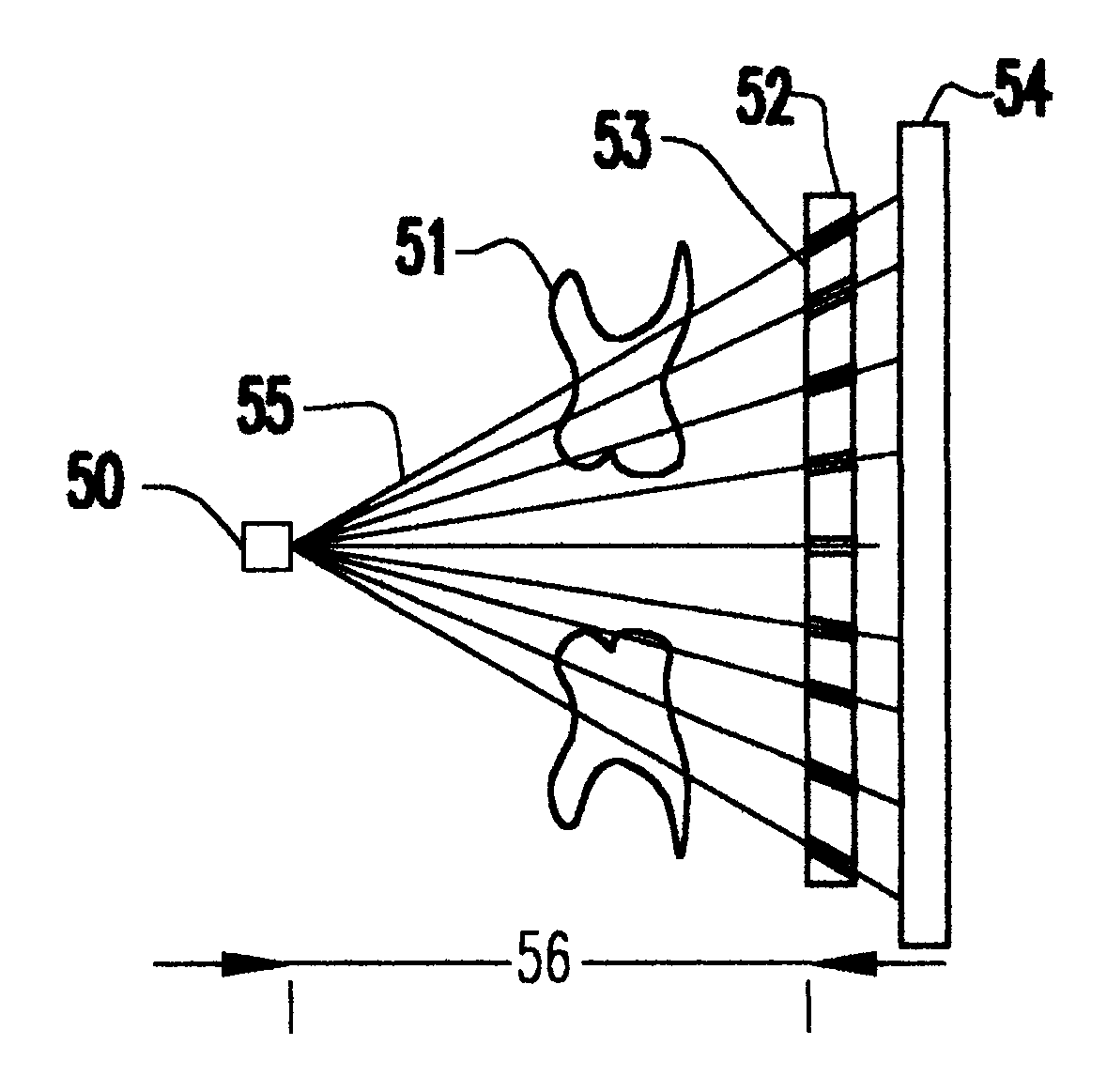
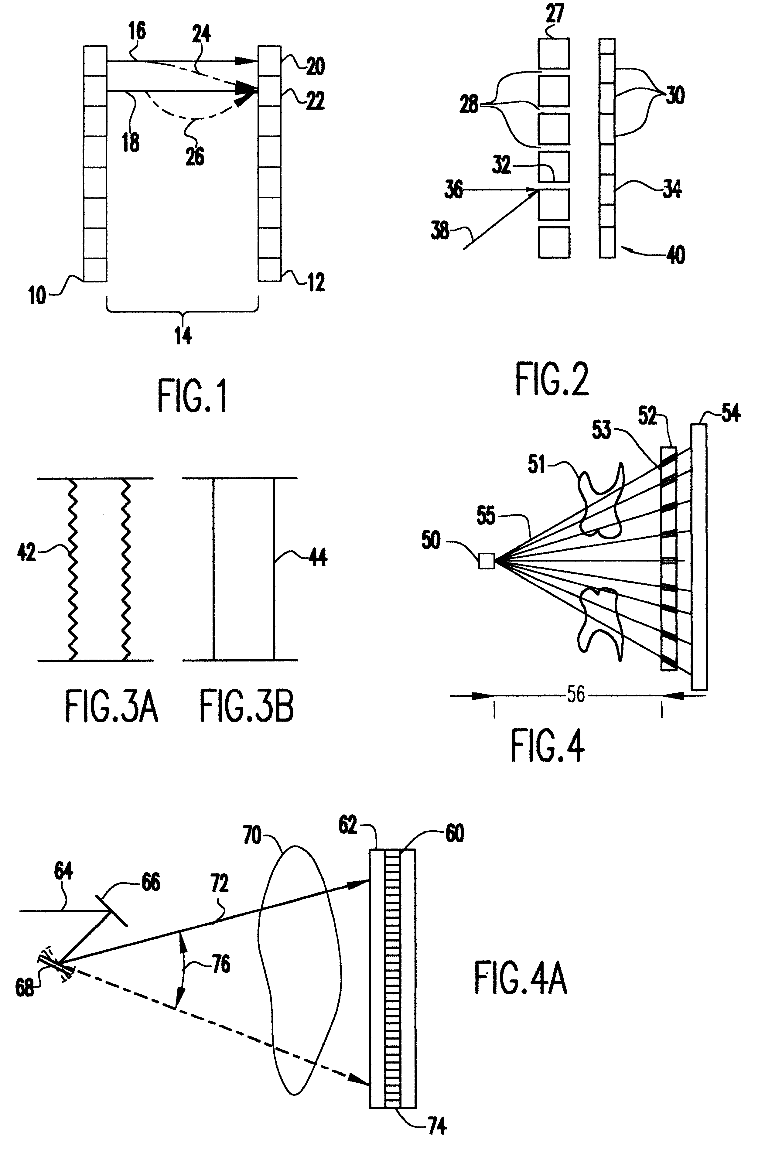
In a variation of the invention, a single light source can be used to produce an accurate two dimensional transillumination image by positioning a light discriminator, equipped with optical passages that are not parallel to each other, between a light source and a detector array. A single light source for providing non-collimated light will produce a fan type beam of light. Optical passages are provided in the mechanical discriminator that will allow only light radially emitted from the light source to pass through and strike the detector array. When a semi opaque object is placed between the light source and the detector array, set at a predetermined distance apart, some light passing through the object will be deflected causing stray light, however; only light traveling radially outward from the light source straight through the object will traverse the discriminator via an optical passage. This configuration is easily set up and less costly than others; however, a predetermined distance must be maintained between the light source and the discriminator and detector. This configuration is particularly well suited for imaging teeth because the light source can be placed outside the mouth thereby alleviating any size constraints. The light source can be for example, a mercury light, a light emitting diode, or any source which produces a suitable light.
In another variation on the invention, alternating emitter-detector arrays are used. Until now, emitter and detector arrays have been grouped primarily with the emitter array on one side of the subject object and the detector array on the other, however arrays containing alternating emitter and detector elements placed on either side of the subject object forming alternating emitter-detector pairs can provide many advantages. One such advantage is that two images may be formed simultaneously. Comparing these two images together will enhance the accuracy of the transillumination imaging process, as well as detection ability. To maintain appropriate positioning the emitter sources and detectors can be mechanically connected. Another advantage is that not only will collimated light be detected and recorded but also reflected light can be detected and analyzed.
A fourth method for producing an image uses a phenomena known in the art as laser speckle. Laser speckles are inherent in any laser image and for most practical purposes are not removable. Lasers use coherent light and since most surfaces posses imperfections and slight differences exist for each ray traveling through a medium, interferences will occur between adjacent rays thus reducing or enhancing detected intensities. Laser speckle is especially prevalent when laser light is detected after passing through an object and subsequently produces different patterns when passed through different mediums. Therefore, the present invention proposes to use the laser speckle phenomena to detect the presence of carcinomas and the like within examined tissue by analyzing the differences in laser speckle patterns after passing through a tissue specimen.

Problems solved by technology

However, one of the drawbacks of using non-ionizing radiation is that it is more easily scattered than ionizing X-rays, thus making it difficult to detect small structures in an object being imaged.
Light passing through the semi opaque object may be deflected causing stray light beams which will result in a distorted image of the object or any anomaly found therein or result in missing an anomaly altogether.
A scan conducted in this manner will result in a thickness contour of the subject object.
While this method does have some degree of error it is more that sufficient for determining the size and location of an anomaly inside a breast, tooth or sample of biological tissue.
Laser speckles are inherent in any laser image and for most practical purposes are not removable.

Method used


Image

  • Transillumination imaging instrumentation with scattered light discrimination
  • Transillumination imaging instrumentation with scattered light discrimination
  • Transillumination imaging instrumentation with scattered light discrimination

Examples


Embodiment Construction

FIG. 1 shows an emitter array 10 spaced away from a detector array 12. Space 14 accommodates an item to be imaged. This invention is primarily directed to biological and medical applications, therefore the arrays 10 and 12 would be positioned to image, for example, a body part or tissue such as a tooth or breast. The emitter array 10 produces a plurality of collimated light beams 16 and 18 which are directed towards specific detectors 20 and 22. Stray light 24 from light beam 16 may be deflected from its intended path towards detector 22 upon encountering an object inside the item being imaged. If this stray light were not discriminated against at detector 22, an object in the path of light beam 18 may not be detected.

As discussed in detail in U.S. Pat. No. 4,945,239 to Wist et al., there are several techniques which can be used to discriminate against stray light beam 24 at detector 22. For example, light 16 could be polarized or have an embedded signal (e.g., pulse code, etc.), an...


PUM


Abstract

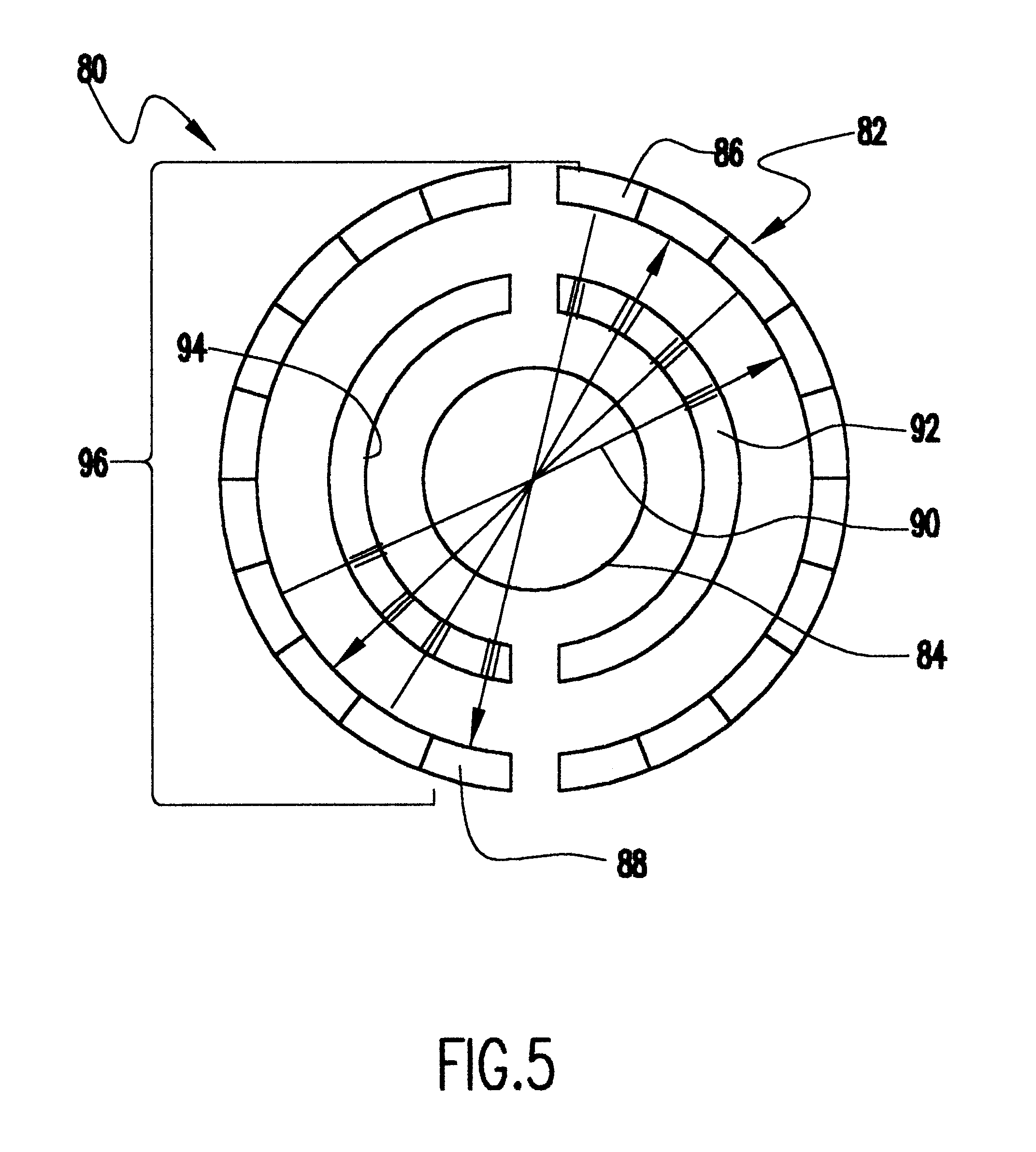
Transillumination imaging instrumentation is improved by eliminating the detection of stray light beams, and facilitating the detection of light beams which pass straight through an illuminated object. Three dimensional images can be constructed using either curved emitter and detector arrays or by using emitter and detector elements that rotate about a common axis.

Description

1. Field of the InventionThe invention generally relates to transillumination imaging instrumentation used in the biological setting and, more particularly, to improvements in the design of transillumination imaging devices to prevent scattered light from adversely affecting detection performance, and provide a more useful format for imagery.2. Description of the Prior ArtTransillumination involves the use of non-ionizing radiation, preferably having wavelengths ranging from 500 nm to 1500 nm, to image an object. Similar to an X-ray, transillumination involves passing radiant energy through an object, and detecting transmitted or reflected radiation. Detection can be accomplished using photocells or other electronic devices, or using photographic film or other image capturing materials. However, particularly when biological imaging is being performed (i.e., breast imaging, teeth imaging, etc.), transillumination offers the advantage of non-ionizing radiation compared to the ionizing...

Claims


Application Information

Patent Timeline
IPC IPC(8): A61B5/00
CPCA61B5/0088
Inventor WIST, ABUND OTTOKAR
Owner WIST ABUND OTTOKAR
Learn More