Method and apparatus for providing high contrast imaging

a high contrast, imaging technology, applied in the field of imaging analysis, can solve the problems of difficult vivo visualization of the circulation, limited resolution of such images, and particular problems of newborns,

Inactive Publication Date: 2002-08-15
INTPROP MVM
View PDF0 Cites 129 Cited by
  • Summary
  • Abstract
  • Description
  • Claims
  • Application Information

AI Technical Summary

Problems solved by technology

Invasive techniques, such as for conventional CBC+Diff tests and bilirubin analysis, pose particular problems for newborns, elderly patients, burn patients, and patients in special care units.
Therefore, in vivo visualization of the circulation is difficult because of poor resolution, and generally impractical because of the complexities involved in compensating for multiple scattering and for specular reflection from the surface.
The resolution of such images is limited because of the scattering of light, and the computations to compensate for scattering are complex.
However, because of its limited dynamic range and inaccuracy, reflection or reflectance spectrophotometry has been used primarily in qualitative rather than quantitative analysis.
Reflectance spectrophotometry is not a primary choice for quantitative analysis because specularly reflected light from a surfac...

Method used


Image

  • Method and apparatus for providing high contrast imaging
  • Method and apparatus for providing high contrast imaging
  • Method and apparatus for providing high contrast imaging

Examples


first embodiment

[0080] a. First Embodiment

[0081] The first embodiment of the present invention is a device (or in vivo apparatus) that provides a high contrast illumination pattern that is projected onto a tissue region of a subject in order to provide an image of blood vessels, blood flow, or tissue contained therein. The in vivo apparatus comprises a light source, an illumination system, and an imaging system. The imaging system includes an imaging detector and its objective.

[0082] The illumination system provides an illumination beam that is used to illuminate a particular blood vessel or tissue area (referred to as the "object") of a patient or subject. The illumination beam propagates along a path or segment referred to as the illumination path. The detector receives light emanating from the object. This light is also referred to as the image beam. The path or segment that the image beam travels is referred to as the image path. According to the present invention, the in vivo apparatus can be ...

second embodiment

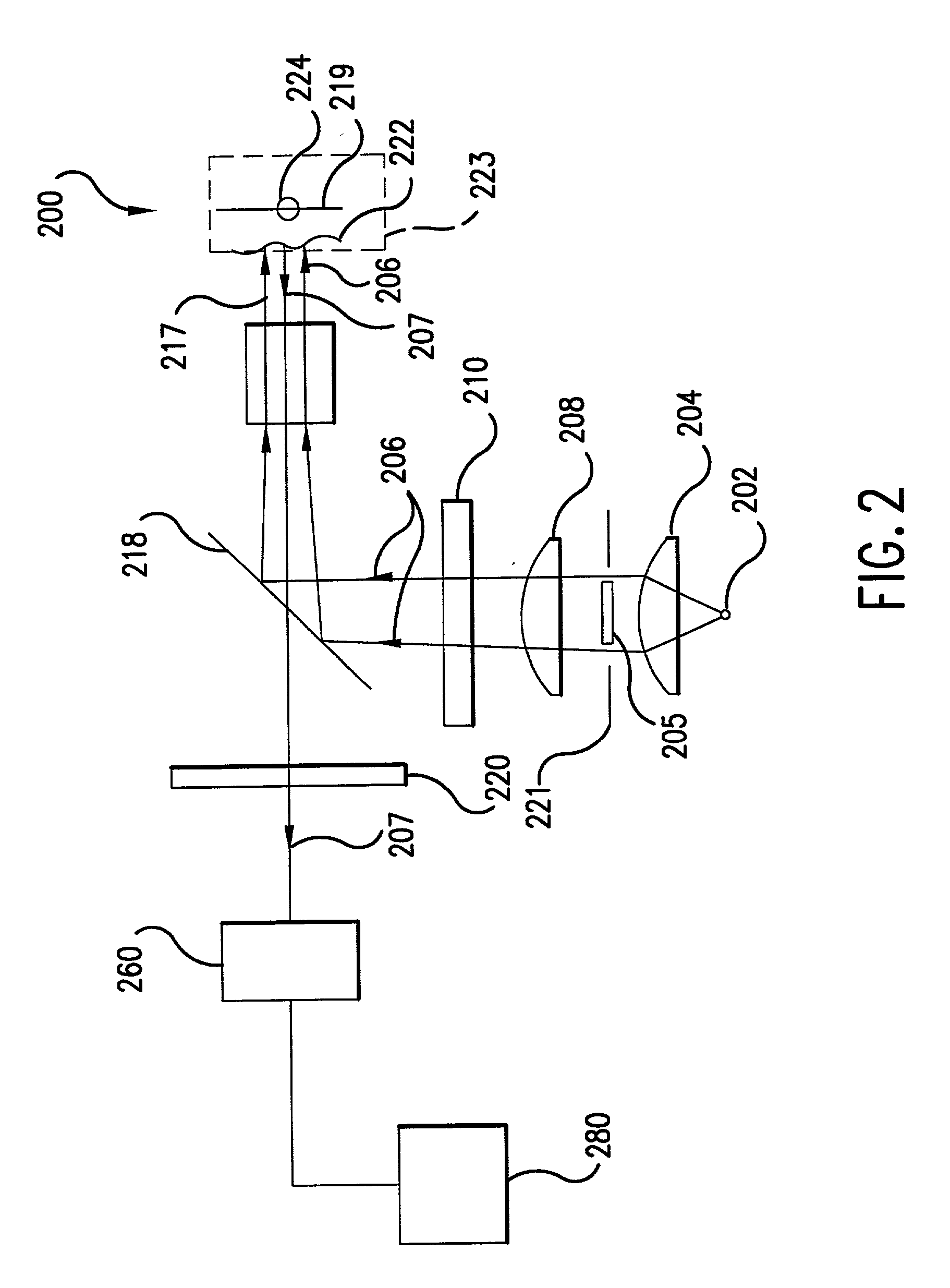
[0109] b. Second Embodiment

[0110] According to a second embodiment of the present invention, the illumination of the tissue region being viewed can be provided in a more efficient manner. For example, device 200 shown in FIG. 2 projects a high contrast illumination pattern onto the tissue region being viewed, thus providing a low rotational effect due to near field tissue birefringence. Yet, apparatus 200 requires a substantial amount of power from light source 202. High output intensity may be needed in order to provide enough illumination to saturate the annular ring outside the FOV of detector 260, which yields enough light into the limiting numerical aperture of the objective lens of the detector. A relatively higher amount of power is required because about 50% of the collimated illumination beam collected by collimating lens 204 is blocked off by obscuration 205.

[0111] For example, assume that illumination source 202 is a tungsten filament, which is a semi-lambertian emitter. ...

third embodiment

[0142] c. Third Embodiment

[0143] According to a third embodiment of the present invention, an imaging system comprises an improved folding mirror or beam splitter. Recall that in FIG. 2, a folding mirror or beam splitter 218 is used to redistribute light from the illumination system to the blood vessel, capillary, or tissue sample being imaged at the object plane. According to this embodiment, rather than using an obscuration or conical lens in combination with a standard 50% reflection 50% transmission beam splitter, an improved folding mirror can transform the illumination beam and project a high contrast illumination pattern onto the object plane. The improved folding mirror or beam splitter can be designed as a mirror that has a completely transmissive center (i.e., having 100% transmission at the wavelength of the illumination and / or image beam). With this approach, a high contrast illumination pattern is imaged onto the object plane and nearly 100% of the intensity of the imag...


PUM


Abstract

An in vivo imaging device having an illumination system that creates a virtual source within a tissue region of a subject in a non-invasive manner. The illumination system transforms a maximum amount of illumination energy from a light source into a high contrast illumination pattern. The illumination pattern is projected onto the object plane in a manner that maximizes the depth to which clear images of sub-surface features can be obtained. The high intensity portion of the illumination pattern is directed onto the object plane outside the field of view of an image capturing device that detects the image. In this configuration, scattered light from within the tissue region interacts with the object being imaged. This illumination technique provides for a high contrast image of sub-surface phenomena such as vein structure, blood flow within veins, gland structure, etc.

Description

[0001] 1. Field of the Invention[0002] The present invention is related to imaging analysis. More particularly, the present invention is related to the use of imaging to perform non-invasive spectral imaging analysis of a subject's vascular system.[0003] 2. Related Art[0004] Most widely accepted methods of blood testing and analysis require invasive and in vitro techniques. For example, a conventional complete blood count including the white blood cell differential (CBC+Diff) test is done in an "invasive" manner in which a sample of venous blood is drawn from a patient through a needle, and submitted to a laboratory for analysis. Alternatively, it is often necessary to measure other types of blood components, such as non-cellular constituents (e.g., blood gases and bilirubin) present in the plasma component of blood. The most common method for bilirubin analysis is through an in vitro process. In such an in vitro process, a blood sample is invasively drawn from the patient. The form...

Claims


Application Information

Patent Timeline
IPC IPC(8): A61B5/00G01N21/27A61B5/026A61B10/00G01N21/21
CPCA61B5/0059A61B5/14535G01N15/0211
Inventor COOK, CHRISTOPHER A.MEYERS, MARK M.
Owner INTPROP MVM
Why Eureka
Try Eureka