
Eureka
For R&D, Eureka makes reading and utilizing patents & technical documents easy.
Eureka AIR
Designed for self-driven R&D workflows. Generate viable solutions, solve complex R&D challenges, empower your innovation with AI.

Eureka Materials
Designed for material experts only. Revolutionize your material R&D, from search, analyze, to developing new materials.

TechResearch
Generate reliable direction feasibility study reports for your R&D in just a few steps.

TechSeek
Discover and master advanced knowledge NOW. Basics, ideas, possibilities, all at once.

TechMind
As an expert in R&D Theories, TechMind can generates customized viable solutions instantly.

TechRisk
Analyze your overall solution with one click, know your potential R&D risks in advance.

TechMonitor
Get weekly tech updates, stay abreast of the latest tech innovations and key insights.
Data transmission device, method and recording medium
- Summary
- Abstract
- Description
- Claims
- Application Information
AI Technical Summary
Benefits of technology
Problems solved by technology
Method used
Image

Examples
first example embodiment
[0037]A first example embodiment according to the present invention is described.
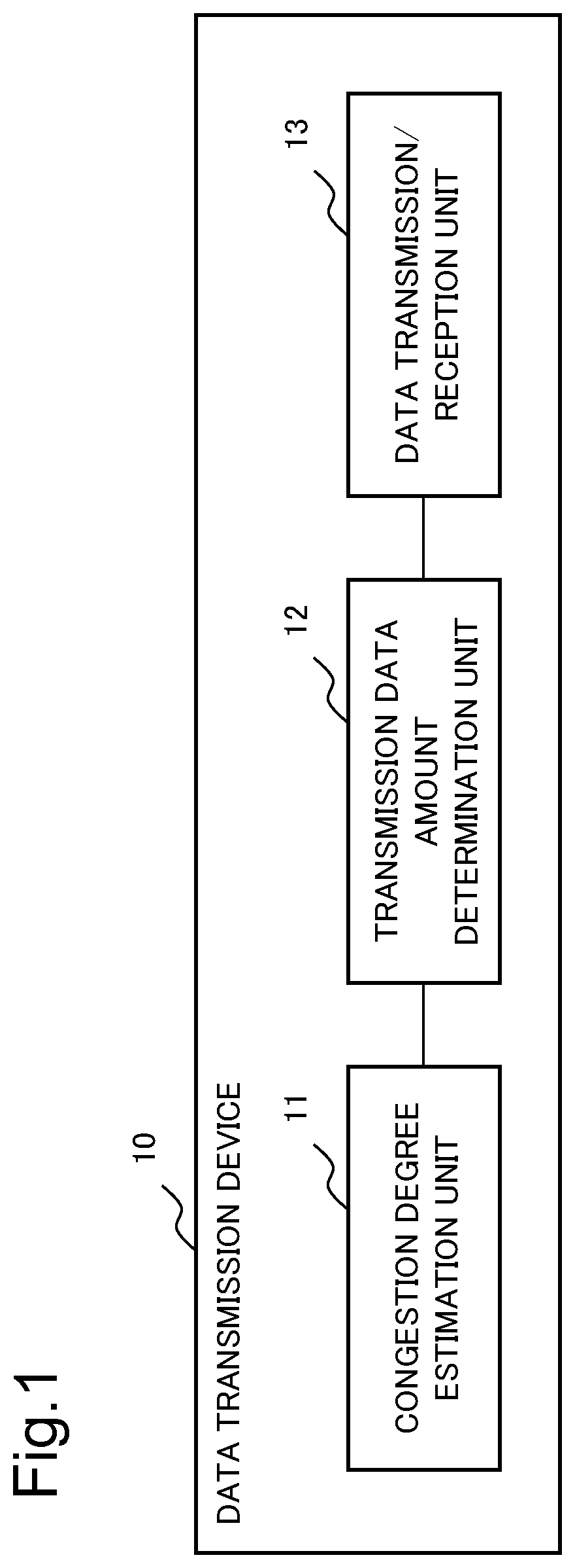
[0038]FIG. 1 illustrates a configuration example of a data transmission device 10 according to the present example embodiment. The data transmission device 10 according to the present example embodiment is constituted by a congestion degree estimation unit 11, a transmission data amount determination unit 12, and a data transmission / reception unit 13.
[0039]The data transmission / reception unit 13 is a unit for performing transmission of transmission data, based on a transmission data amount. The congestion degree estimation unit 11 is a unit for estimating a congestion degree of at least a part of communication sessions in which a communication resource to be used in an own session to be used in transmission of transmission data is shared, based on communication quality measurable by the data transmission device 10 itself and relating to the transmission of the transmission data. The transmission data am...
second example embodiment
[0046]Next, a second example embodiment according to the present invention is described. In the present example embodiment, a data transmission device is more specifically described.
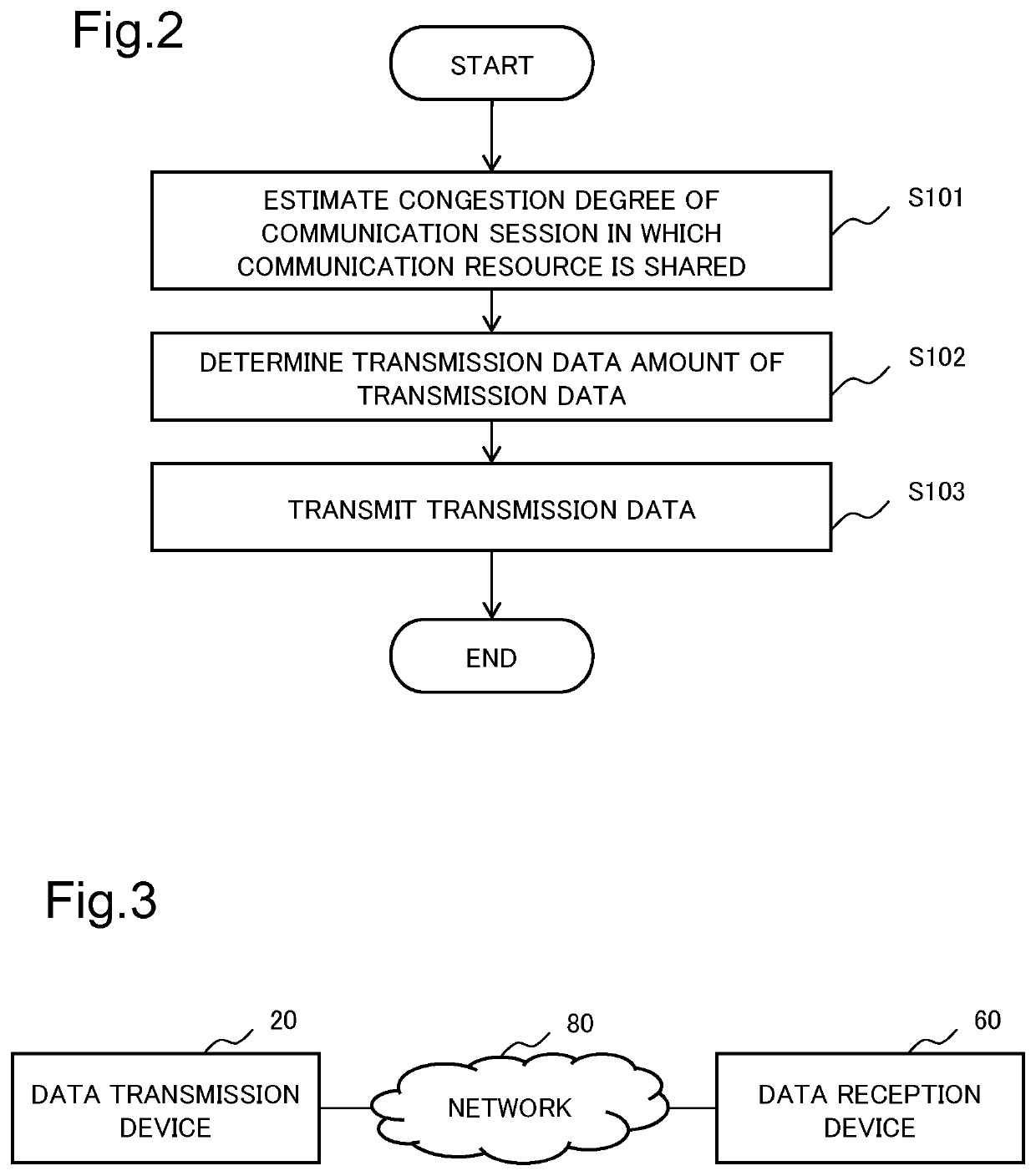
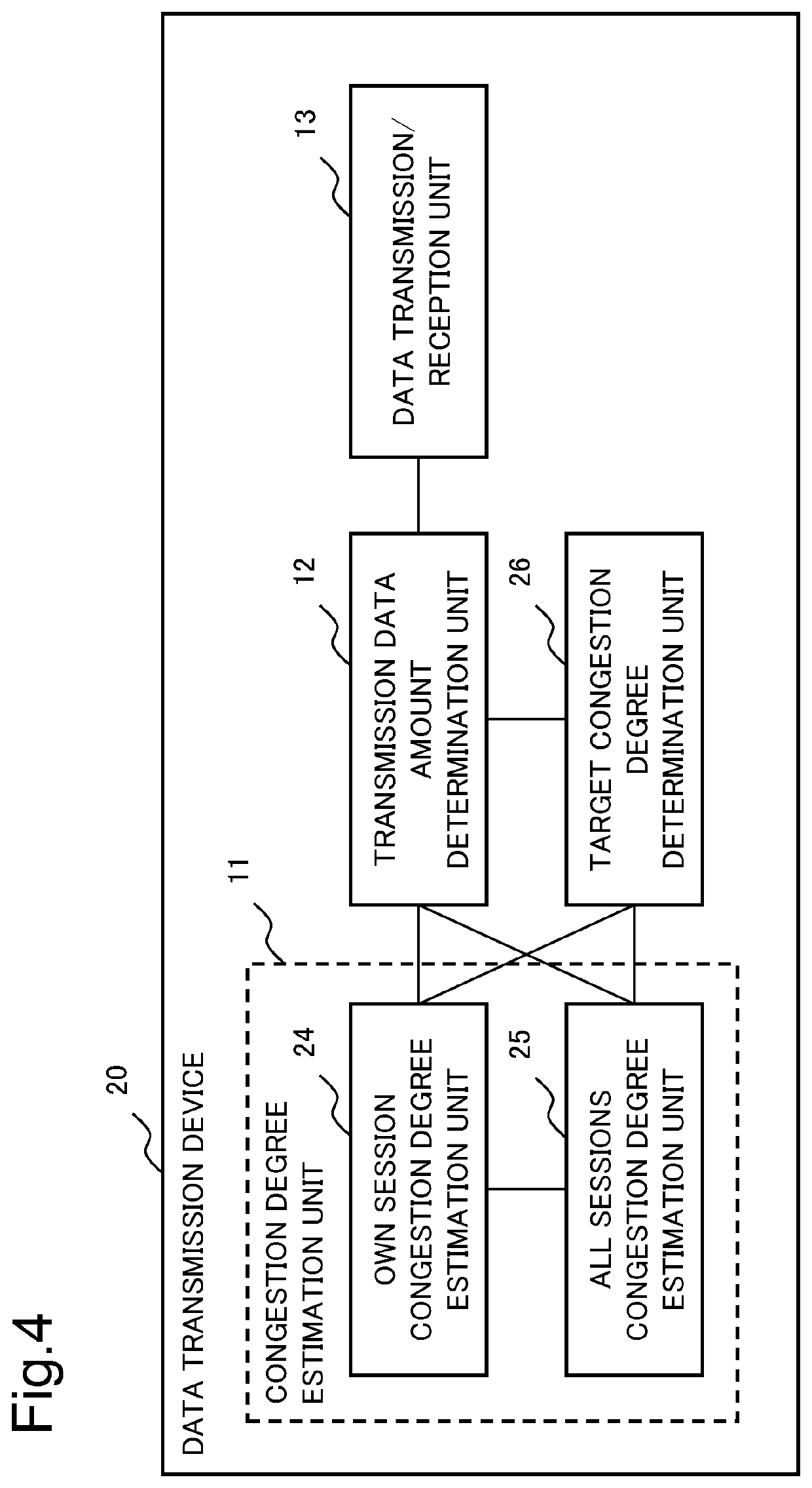
[0047]FIG. 3 illustrates a configuration example of a data transmission system employing a data transmission device 20 according to the present example embodiment.
[0048]The data transmission device 20 is a data transmission device for transmitting requested data by establishing connection such as a TCP with respect to a data reception device 60.
[0049]The data transmission device 20 can be functioned as an origin server for storing data requested from a user, for example. Further, the data transmission device 20 can be functioned as a relay server device, which is disposed within a network 80, such as a cache server, a proxy server, or an edge server, for example, and configured to temporarily terminate data communication between an origin server and the data reception device 60.
[0050]Note that the data t...
third example embodiment
[0142]Next, a third example embodiment according to the present invention is described. The present example embodiment is an example of a case that there are a plurality of own sessions in which a data transmission device transmits transmission data, and the own sessions are divided into a plurality of groups by a transmission control parameter or the like.
[0143]FIG. 7 illustrates a configuration example of a data transmission device 30 in the present example embodiment. The data transmission device 30 in the present example embodiment is constituted by a data transmission / reception unit 13, an associated function group determination unit 38, and transmission control function groups 39 (39-1 to 39-N). Each of the transmission control function groups 39 includes a congestion degree estimation unit 11 and a transmission data amount determination unit 12. Note that each of the transmission control function groups 39 may further include a target congestion degree determination unit 26.
[...
PUM
 Abstract
Description
Claims
Application Information
 - R&D Engineer
- R&D Manager
- IP Professional
- Industry Leading Data Capabilities
- Powerful AI technology
- Patent DNA Extraction
Browse by: Latest US Patents, China's latest patents, Technical Efficacy Thesaurus, Application Domain, Technology Topic, Popular Technical Reports.
© 2024 PatSnap. All rights reserved.Legal|Privacy policy|Modern Slavery Act Transparency Statement|Sitemap|About US| Contact US: help@patsnap.com