
Laminated glazing with embedded data transponder

Active Publication Date: 2020-06-18
SAINT-GOBAIN GLASS FRANCE
View PDF6 Cites 5 Cited by
  • Summary
  • Abstract
  • Description
  • Claims
  • Application Information

AI Technical Summary

Benefits of technology

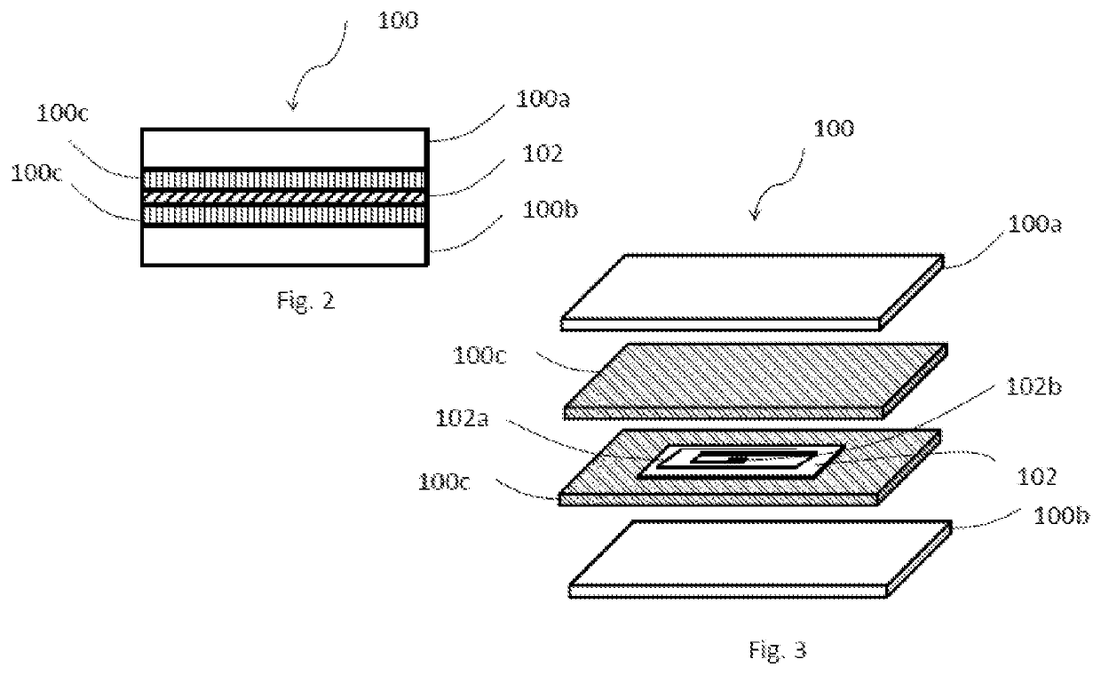
The patent text describes a laminated glazing that includes a first and second substrate with one or more interlayers between them. The interlayers can contain a data transponder device with an antenna and an integrated circuit. The laminated glazing can also contain a heating element between the substrates. The method of manufacturing involves assembling the substrates and data transponder device, and then subjecting it to de-airing and autoclaving to form the integrated laminated glazing. The technical effects include improved thermal insulation and protection of the data transponder device.

Problems solved by technology

However, these RFID or NFC stickers come with several limitations.
For instance, these stickers can be removed or tampered easily due to ageing, weathering, theft, or damage due resulting from external factors such as wind, rain, or vandalism.
Moreover, it is very difficult to stick these stickers having the data transponders, once peeled off from the vehicle windshield.
Thus results in wastage of these stickers.
The other limitation is the durability of the antenna, which has the tendency to degrade in terms of readability over a period.
The difficulty of removing expired stickers is also a disadvantage, as it is difficult to remove adhesive or sticky residue or remnants of the sticker from the automobile glazing.
In addition to this, there are many significant drawbacks in this prior-art.
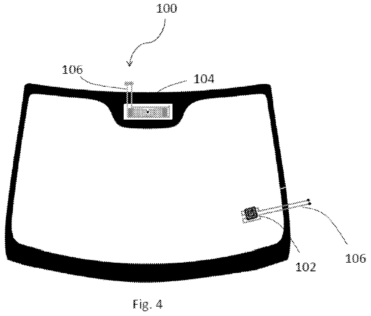
Firstly, '157 is not dealing with improving durability and data readability of the data transponders in harsh conditions such as colder weather conditions wherein temperature goes well below 0° c. Moreover, the above mentioned prior art is not providing the ideal location for placing the data transponders within the laminated glazing.

Method used


Image

  • Laminated glazing with embedded data transponder
  • Laminated glazing with embedded data transponder
  • Laminated glazing with embedded data transponder

Examples


example 1

tability Test

[0048]The data transponder embedded laminated glazing samples were kept at 80° C. for 24 hours and the effect on the read range, readability counts, location for data transponder in the laminated glazing and data integrity was checked. Table 1 shows the different parameters checked after the samples were kept at 80° C. for 24 hours.

TABLE 1Read-SampleDataReadabilityNo.LocationIntegrityRangeCountSample 1Inner face of first substrateYes14.54274Sample 2Inner face of second substrateYes14.53449Sample 3Between two interlayersYes14.55925

Results from storage stability test (Table 1) showed that the readability was higher when the data transponder device embedded between two interlayers of the laminate glazing. In addition to this, when the data transponder device was embedded on the inner face of the first substrate, higher data readability was achieved.

example 2

stance Test

[0049]The data transponder embedded laminated glazing samples were kept at 100° C. for 400 hours and the effect on the read range, readability counts, location for data transponder in the laminated glazing and data integrity was checked. Table 2 shows the different parameters checked after the samples were kept at 100° C. for 400 hours.

TABLE 2Read-SampleDataReadabilityNo.LocationIntegrityRangeCountSample 1Inner face of first substrateYes159029Sample 2Inner face of second substrateYes1510006Sample 3Between two interlayersYes1510537

Results from heat resistance test (Table 2) showed that the readability was higher when the data transponder device embedded between two interlayers of the laminate glazing. In addition to this, when the data transponder device was embedded on the inner face of the second substrate, higher data readability was achieved.

example 3

ycle Resistance Test

[0050]The data transponder embedded laminated glazing samples were kept at following conditions firstly 30° C. for 2 hours, secondly room temperature for 30 minutes, thirdly 100° C. for 2 hours and finally room temperature for 30 minutes. The effect on the read range, readability counts, location for data transponder in the laminated glazing and data integrity was checked for the samples. Table 3 shows the different parameters checked after the samples were subjected to above mentioned conditions.

TABLE 3Read-SampleDataReadabilityNo.LocationIntegrityRangeCountSample 1Inner face of first substrateYes14.518852Sample 2Inner face of second substrateYes14.511484Sample 3Between two interlayersYes14.51806

Results from thermal cycle resistance test (Table 3) showed that the readability was higher when the data transponder device embedded on the inner face of the first substrate of the laminate glazing. In addition to this, when the data transponder device was embedded on t...


PUM

PropertyMeasurementUnit
Thicknessaaaaaaaaaa
Thicknessaaaaaaaaaa
Frequencyaaaaaaaaaa

Abstract

A laminated glazing includes a first substrate having an outer face and an inner face, one or more interlayers disposed on the inner face of the first substrate, a second substrate disposed on the interlayer and at least one data transponder device. The date transponder device includes an antenna and an integrated circuit that is provided between the first substrate and the second substrate Optionally, one or more heating elements is / are provided between the first substrate and the second substrate and spaced around the data transponder device at a pre-defined distance for rapidly heating the antenna the data transponder.

Description

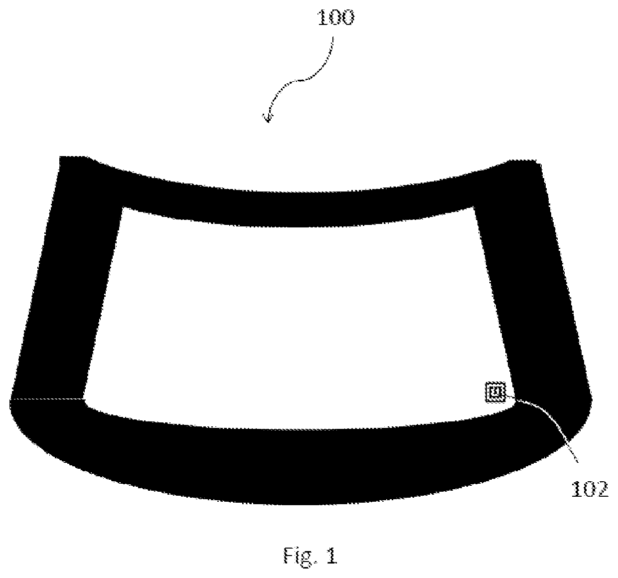
TECHNICAL FIELD[0001]The present disclosure relates generally to a laminated glazing of a vehicle embedded with one or more data transponders and more particularly to a laminated glazing with better readability performance of the data transponders in extreme weather conditions.BACKGROUND[0002]Background description includes information that may be useful in understanding the present disclosure. It is not an admission that any of the information provided herein is prior art or relevant to the presently claimed invention, or that any publication specifically or implicitly referenced is prior art.[0003]Currently RFID and NFC tags provided on the vehicle windshields in the form of stickers and used as a data storage device to store vehicle related data or information.[0004]However, these RFID or NFC stickers come with several limitations. For instance, these stickers can be removed or tampered easily due to ageing, weathering, theft, or damage due resulting from external factors such as...

Claims


Application Information

Patent Timeline
IPC IPC(8): G06K19/077B32B27/36B32B27/30B32B17/10
CPCB32B17/10036G06K19/0772B32B2369/00B32B17/10293B32B27/304B32B17/10018B32B2457/00B32B17/10678B32B27/365G06K19/07773B32B17/1055G06K19/07749G06K19/07722G06K17/00G02B1/10G02B5/208B32B17/10348G02B27/01B32B27/32G02B2027/0194
Inventor THANGAMANI, ARUNVELRICHARDSON D, SAMSONTAMALAPAKULA, JYOTHI LATHAN, KASINATHJAYARAM, ROBIN C
Owner SAINT-GOBAIN GLASS FRANCE
Learn More