
Systems and methods to temporarily alter traffic flow

Active Publication Date: 2020-06-18
STC INC
View PDF8 Cites 6 Cited by
  • Summary
  • Abstract
  • Description
  • Claims
  • Application Information

AI Technical Summary

Benefits of technology

This patent describes a method for controlling traffic in a roadway system using a computer system. The method allows a target vehicle to operate safely within the system by automatically controlling its movement based on pre-defined rules. The system can also detect and monitor the movement of other vehicles and quickly make changes to the control pattern to avoid collisions or traffic jams. The technical effect of this method is to create a clear path for the target vehicle and prevent other vehicles from interfering with its movement, resulting in increased safety and efficiency on the road.

Problems solved by technology

In other instances, intersections may be entirely uncontrolled, and drivers are expected to be alert and manage cross traffic in the intersection.
For example, at a railroad crossing, trains are generally incapable of stopping in time to prevent a collision at an intersection, and the energy requirements for stopping and restarting a train are high as compared to vehicular traffic.
However, the problem with these types of laws is that they require a clear modification of default right-of-way and it is possible that drivers may not consistently or correctly apply these special rules, instead following the established default.
Further, as traffic signals become more complex, often utilizing right and left turn arrows and controls for individual lanes, these “simple” rules altering the default can become difficult for drivers to consistently and correctly apply ad hoc.
The rules for clearing traffic when an emergency vehicle approaches are clear, if sometimes difficult to apply, but the rules for restoring the ordinary flow of traffic in the wake of a passing emergency vehicle are less clear, and uncertainty among drivers attempting to reestablish normal traffic flow can itself increase the risk of collisions.
A problem with these systems is that they merely provide traffic flow “pauses” while an emergency vehicle (or other exception to normal traffic flow) passes, and only deal with the issue at one intersection.
However, an additional question lies with how to manage the westbound light applicable to the emergency vehicle.
These stopped vehicles may not be able to easily get out of the way because in congested, traffic-dense areas, there is little space for them to move.
Further, in roadways with a center median barrier, the emergency vehicle may not be able to enter oncoming traffic lanes, and thus an emergency vehicle may become stuck behind traffic because of the priority system altering the default right-of-way.
However, if the emergency vehicle is traveling at a higher rate of speed compared to the rest of the traffic, this can present a dangerous situation, because the drivers in front of the emergency vehicle may be alert to the vehicle's approach and not know whether to proceed into the intersection (the default situation provided by the signal) or stop and get out of the way (the generally understood exception when an emergency vehicle is approaching), which can also present a dangerous situation.
This presents a high stress situation for the driver and a concern for the emergency vehicle driver, who does not know how other drivers will respond, yet must proceed toward the intersection at high speed to reach the emergency quickly.
Further, while the above circumstances produce confusion, they at least all relate to an emergency vehicle where, at least the intended, modifications to signal based right-of-way are generally known to drivers.
However, there also are a number of other traffic circumstances where there is no generally accepted modification or exception to traffic flow, or drivers have no idea that a modification to the default rules is desirable.
Such circumstances may occur infrequently enough that drivers usually do not know how to respond when they do happen.
In effect, these types of situations present confusion because priority systems attempt to use a default right-of-way signaling system to implement a change to right-of-way, but only in a limited “bubble” surrounding a monitored vehicle.
To put it another way, the problems arise because the right-of-way rules in a priority modification are only temporarily paused, and are only paused generally at a single intersection towards which a specific monitored vehicle is approaching.
The problems, thus, effectively exist because other vehicles are moving into and out of the area in which the priority vehicle has priority.
As other drivers need to now interact with the priority vehicle, this creates confusion.
Removing other traffic from an area, however, has traditionally caused major disruptions to traffic flow and can only be provided through specific interventions.
However, this type of solution doesn't work for unscheduled events, such as emergencies, and is not resource-efficient for infrequent, small scale traffic disruptions like a funeral procession.
While the above is an effective methodology to radically alter traffic flow and provide for an area of roadway with no traffic on it, it is slow to implement and incredibly resource intensive.
Further, in many instances, the electrical signals required to implement such a system simply do not exist because it is not cost-effective to add an electric traffic control to roads to deal with this infrequent circumstance.
Such signal lights would rarely be used, and the overhead of installing and maintaining them is unlikely to justify the marginal gain realized from such infrequent use.
Thus, a traffic control system is typically not configured to, or even capable of, temporarily suspending the ordinary traffic flow plan in order to allow temporary passage of a vehicle or set of vehicles in a situation where the path of the vehicle is cleared.

Method used


Image

  • Systems and methods to temporarily alter traffic flow
  • Systems and methods to temporarily alter traffic flow
  • Systems and methods to temporarily alter traffic flow

Examples


Embodiment Construction

)

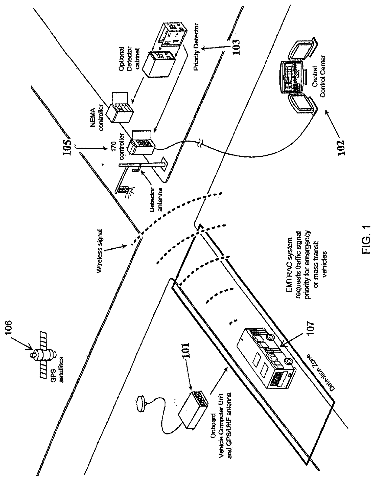
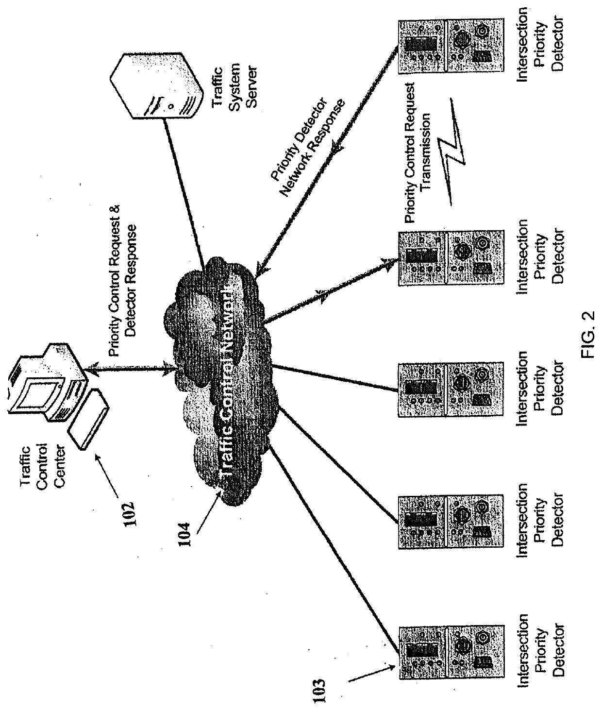
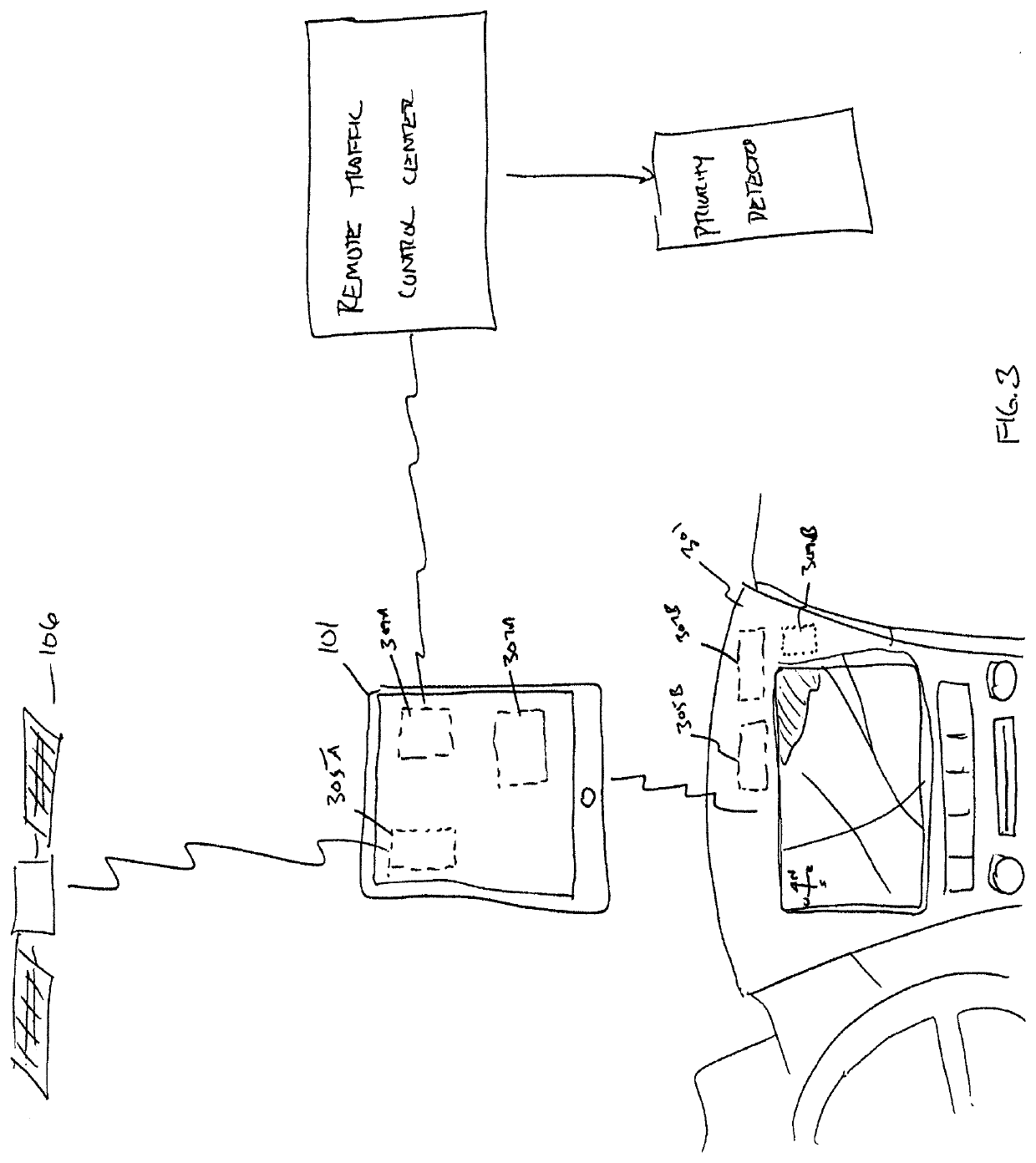
[0053]This following detailed description and disclosure are intended to teach by way of example and not by way of limitation. As a preliminary matter, it should be noted that, while the description of various embodiments of the disclosed system will discuss the movement of various special-purpose vehicles (such as, but not limited to, emergency vehicles, maintenance vehicles, and mass transit vehicles, buses, light rail trains, and street cars) through signal lights, this in no way limits the application of the disclosed traffic control system to such uses. Any vehicle which could benefit from the traffic control systems and methods described herein is contemplated.

[0054]The traffic control system described herein is an improvement upon systems described in U.S. Pat. Nos. 8,878,695, 8,773,282, 9,330,566 and 9,916,759. The entire disclosure of all of these documents is incorporated herein by reference. An embodiment is shown in FIGS. 1-3. In the depicted embodiment, the hardware co...


PUM


Abstract

A method for permitting a target vehicle to safely violate a right-of-way system of rules is described. The method may comprise, amongst other things, providing a roadway system, wherein the movements of vehicles within the roadway system are governed by a right-of-way system of rules; controlling a traffic control system including a plurality of traffic control signals in a manner that causes the plurality of traffic control signals to change in accordance with default control pattern for implementing the right-of-way system of rules; and modifying the default control pattern. By doings so, the method may permit a target vehicle to safely violate the right-of-way system of rules. Similarly, by doing so, the method may prevent a plurality of secondary vehicles from traveling along or through a predicted path of the target vehicle.

Description

CROSS-REFERENCE TO RELATED APPLICATIONS[0001]This application claims the benefit of U.S. Provisional Patent Application No. US 62 / 779,935 titled SYSTEMS AND METHODS TO TEMPORARILY ALTER TRAFFIC FLOW, filed Dec. 14, 2018, the entire contents of which are hereby incorporated by reference herein.BACKGROUND1. Field of the Invention[0002]This disclosure is related to the field of traffic signal and control systems, and more specifically to systems and methods for temporarily altering or suspending normal traffic flow.2. Description of the Related Art[0003]The need to manage traffic in roadways is self-evident. Streets are more congested than ever and effective use of traffic control systems can reduce commute times, pollution, and accidents, and increase the overall efficiency of a roadway system.[0004]Historically, traffic management was conducted by traffic police, who physically stood in intersections and directed traffic using hand signals or flags. Later, illuminated traffic signals...

Claims


Application Information

Patent Timeline
IPC IPC(8): G08G1/081G08G1/095G08G1/087
CPCG08G1/095G08G1/087G08G1/081
Inventor CROSS, BRAD
Owner STC INC
Learn More