
Distributed optical sensing systems and methods

a distributed sensing and optical path technology, applied in the field of optical path length change measurement systems and methods, can solve the problems of inability to accurately and unambiguously measure optical path length change, inability to provide a distributed sensing method, and higher cost and complexity of the system being used

Active Publication Date: 2020-07-02
TERRA15 PTY LTD
View PDF0 Cites 14 Cited by
  • Summary
  • Abstract
  • Description
  • Claims
  • Application Information

AI Technical Summary

Benefits of technology

The present invention senses changes in the optical path length in a way that allows the measurement of multiple physical parameters in a transparent medium. This can include longitudinal strain, transverse strain, acoustic waves, seismic waves, vibration, motion, bending, torsion, temperature, optical delay, and chemical composition. The invention uses a special light source and measures the scattered backlight from the medium with high accuracy. This allows for the quantitative and distributed measurement of optical path length changes, which can be useful in various applications.

Problems solved by technology

Both Sikora and Healey, however, rely exclusively on detecting an intensity variation of backscattered light to detect a disturbance, using only one intensity detector which is incapable of directly measuring phase.
It is therefore not possible to accurately and unambiguously measure optical path length change (or other physical parameters such as strain) in practical operation.
Thus the methods taught by Sikora and Healey do not provide a means of distributed sensing, for example, measuring multiple optical path length changes within a sensing medium.
However, they rely on bidirectional or counter-propagating optical paths to exploit the Sagnac effect and are not obviously extended to distributed backscattering situations; where access to both ends of the sensing fibre is not provided.
The advancements in technology to enable these applications has resulted in higher cost and complexity of the systems being used.
However, all the previous DAS systems suffer from the same disadvantage that the coherence length, and associated phase noise, of the optical source is a major factor in limiting the signal-to-noise of the system and thereby limiting sensitivity.
Of course, requiring the source optical signal to satisfy such high coherence length parameters, adds significant complexity and cost to the overall DAS system.
A further disadvantage of existing DAS systems is a limit on the optical power that may be delivered to the sensing medium (e.g. an optical fibre) before non-linear interactions between the forward propagating light and the sensing medium itself, which, can limit the optical power which can propagate beyond 10s or 100s of meters or introduce phase and intensity modulations which corrupt the Rayleigh backscatter signal.
A typical non-linear effect in optical fibres is the so-called modulation instability, which can induce a position-dependent signal fading in long-range DAS systems.
This fading leads to a complete masking of the interference signal at some positions and therefore to a loss of sensitivity at those positions.
Another typical non-linear effect in optical fibres that can be particularly limiting is Brillouin scattering, which can exhibit an appreciable effect resulting in loss of the Rayleigh backward propagating signal at input power levels as little as 100 mW.
Since the Rayleigh backscatter is a very weak phenomenon, this directly limits the sensitivity of the system, by limiting the amount of optical power that can be used in the sensing fibre.
Generally, in c-OTDR and c-OFDR, low coherence of the laser impacts directly and negatively on the phase noise of the measurement and therefore severely limits the sensitivity of the system.
On the other hand, high coherence of the laser typically results in higher costs, higher complexity and poor system robustness during transportation or operation in uncontrolled environments.
Vibration of the source or system can severely hinder system performance.
Furthermore, narrowband / narrow-linewidth and thus, highly coherent, laser sources suffer from lower non-linear thresholds in optical fibre, such as stimulated Brillouin scattering, four-wave mixing and modulation instability, which limit the optical power that can be launched into the fibre.
The coherence requirements on the source also make it difficult to modulate the source directly without worsening the coherence.
Thus, external modulators are required which adds to the cost and complexity of the system.
Yet another limitation of using nearly monochromatic or coherent light sources for DAS is that the Rayleigh backscatter from an optical fibre exhibits random amplitude variations along the fibre.
This is a significant source of error in coherent optic al-time-domain-reflectometry (c-OTDR) and coherent optical-frequency-domain-reflectometry c-OFDR systems and negatively impacts system sensitivity.
Multiple high-coherence sources and multiple frequencies introduces significant cost and complexity to DAS systems.

Method used


Image

  • Distributed optical sensing systems and methods
  • Distributed optical sensing systems and methods
  • Distributed optical sensing systems and methods

Examples


Embodiment Construction

[0146]It should be noted in the following description that like or the same reference numerals in different embodiments denote the same or similar features.

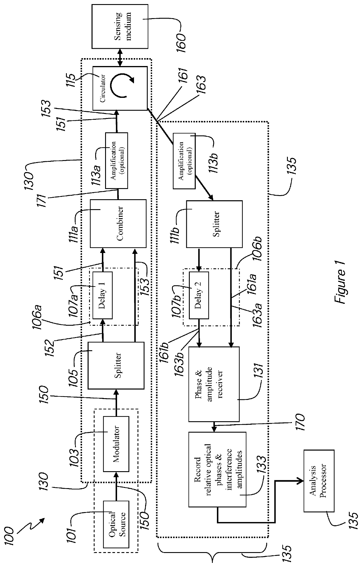
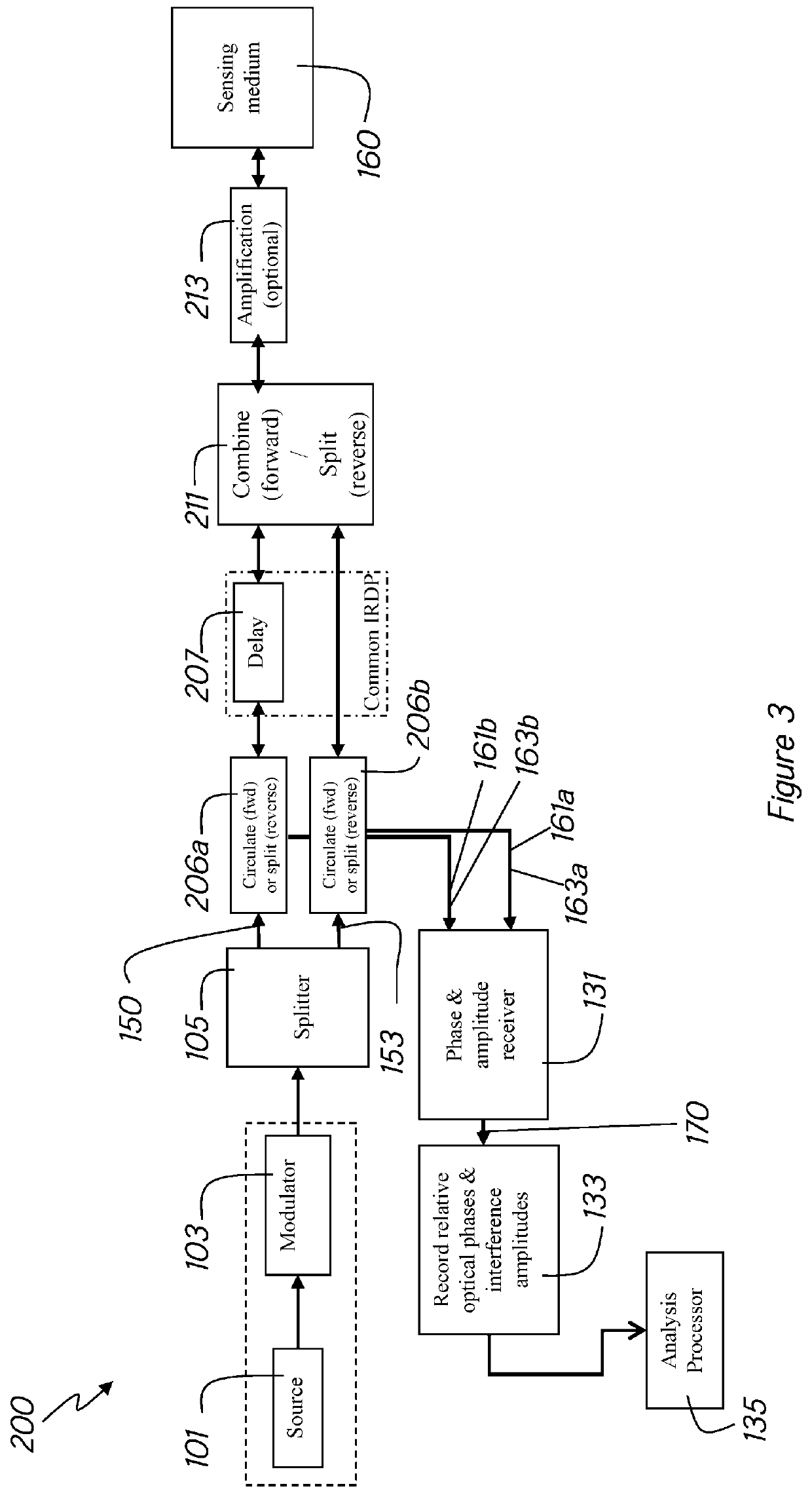
[0147]Disclosed herein are systems and methods for quantitative distributed acoustic sensing (DAS) systems for quantitative distributed measurement of optical path length changes along a sensing medium such as, for example an optically transparent medium such as an optical fiber.

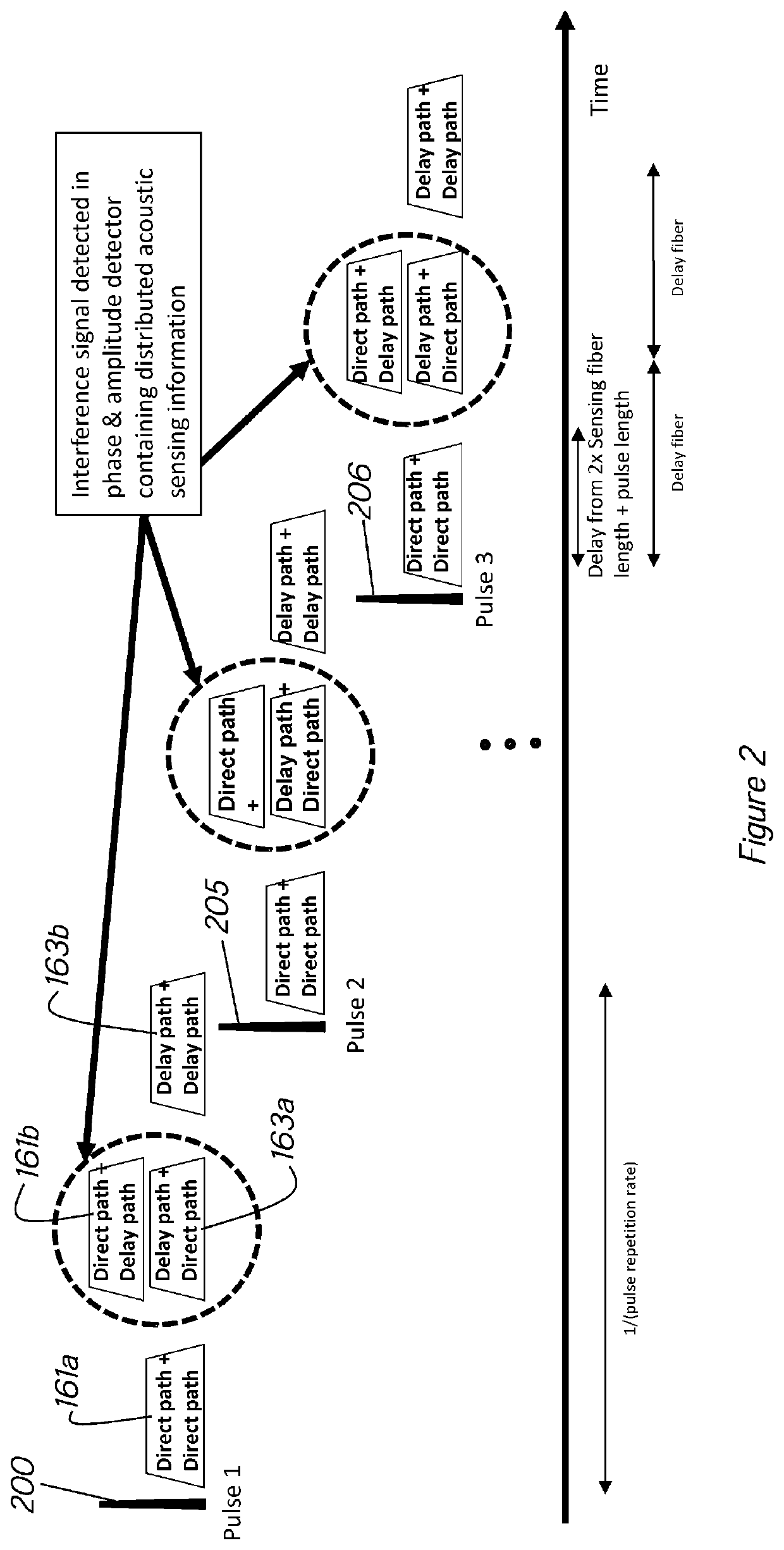
[0148]The DAS system disclosed herein comprises a broadband optical source and phase and amplitude measurement capable of accurately measuring phase. The broadband optical source may have a coherence time, τcoh and, interchangeably, a coherence length, lcoh, defined as the optical path length corresponding to propagation in a medium for a time equal to the coherence time. There is no in-principle lower bound on the coherence length of the source when used in the systems and methods disclosed herein. Coherence time, τcoh, is calculated by dividing the cohe...


PUM


Abstract

A distributed optical detection system comprising: a broadband optical source; and a phase and amplitude receiver for measuring phases and amplitudes of distributed backscattered signals from a sensing medium. Methods of quantitatively sensing optical path length changes along a sensing medium in a distributed manner are also disclosed.

Description

FIELD OF THE INVENTION[0001]The present invention relates to systems and methods for quantitative and distributed measurement of optical path length changes in an optically transparent medium and in particular to systems and methods for quantitative and distributed measurement of optical phase variations along an optical path in an optically transparent medium.[0002]The invention has been developed primarily for use in methods and systems for quantitative and distributed sensing of optical path length changes along an optical fibre caused by acoustic, elastic, seismic, vibrational, thermal or kinetic energy and will be described hereinafter with reference to this application. However, it will be appreciated that the invention is not limited to this particular field of use.BACKGROUND[0003]Any discussion of the background art throughout the specification should in no way be considered as an admission that such background art is prior art, nor that such background art is widely known o...

Claims


Application Information

Patent Timeline
Patent Type & Authority Applications(United States)
IPC IPC(8): G01D5/353
CPCG01D5/35361G01D5/353G01D5/35306G01H9/004G01K11/32G01B11/18G01D5/35358Y02B10/30
Inventor ISSA, NADERROELENS, MICHAEL ALBERIC FREDDYFRISKEN, STEVEN JAMES
Owner TERRA15 PTY LTD
Learn More