Multi-system integrated antenna

a multi-system integrated, antenna technology, applied in the field of communication, can solve the problems of inability to achieve high-gain multi-system integrated antennas, limited number of high low-frequency antenna array elements, etc., and achieve the effect of increasing the gain of antennas and facilitating the acquisition of superior performance indexes

Inactive Publication Date: 2020-07-16
COMBA TELECOM TECH (GUANGZHOU) CO LTD
View PDF0 Cites 5 Cited by
  • Summary
  • Abstract
  • Description
  • Claims
  • Application Information

AI Technical Summary

Benefits of technology

[0022]The solution of the present application possesses the following advantages:
[0023]1. The present application sets the intelligent antenna arrays and the base station antenna arrays operating in different frequency bands at different ends of the reflective plate, and the array elements of at least one base station antenna array enclose the array elements of the plurality of intelligent antenna arrays therein. By fully utilizing the gaps between the antenna array elements, one or more base station antenna array elements are added while maintaining the size of the radome and the reflective plate unchanged, thereby increasing the gain of the antenna.
[0024]2. In the multi-system integrated antenna of the present application, since the space occupied by the plurality of intelligent antenna array elements is adjacent to the space required by the single base station antenna array element, the design not only may utilize the space reasonably, but also may ensure that the performance of the embedded base station antenna array elements is basically the same as that of the ordinary base station antenna array elements.
[0025]3. Since the intelligent antenna array and the base station antenna array of the present application are respectively disposed at different ends of the reflective plate, only a few array elements of the intelligent antenna array are enclosed by the base station antenna array elements adjacent to the intelligent antenna array, and for the intelligent antenna array having a plurality of intelligent antenna array elements, the base station antenna array has less influence on it, such that it is easier to obtain superior performance indexes.

Problems solved by technology

However, in order to balance the gain, upper sidelobe suppression after the electric downtilt and other indexes, the selection range of the low frequency band radiation array spacing is generally 250 mm˜300 mm, and the selection range of the high frequency band radiation array spacing is generally 105 mm˜115 mm, and the length of the radome is generally limited to 2 m or less, so the number of high frequency antenna array elements and low frequency antenna array elements is limited.
When the number of array elements of the array antenna is limited, the antenna gain corresponding to the array antenna is also limited, such that a high-gain multi-system integrated antenna cannot be realized in one radome.

Method used


Image

  • Multi-system integrated antenna
  • Multi-system integrated antenna

Examples


embodiment 1

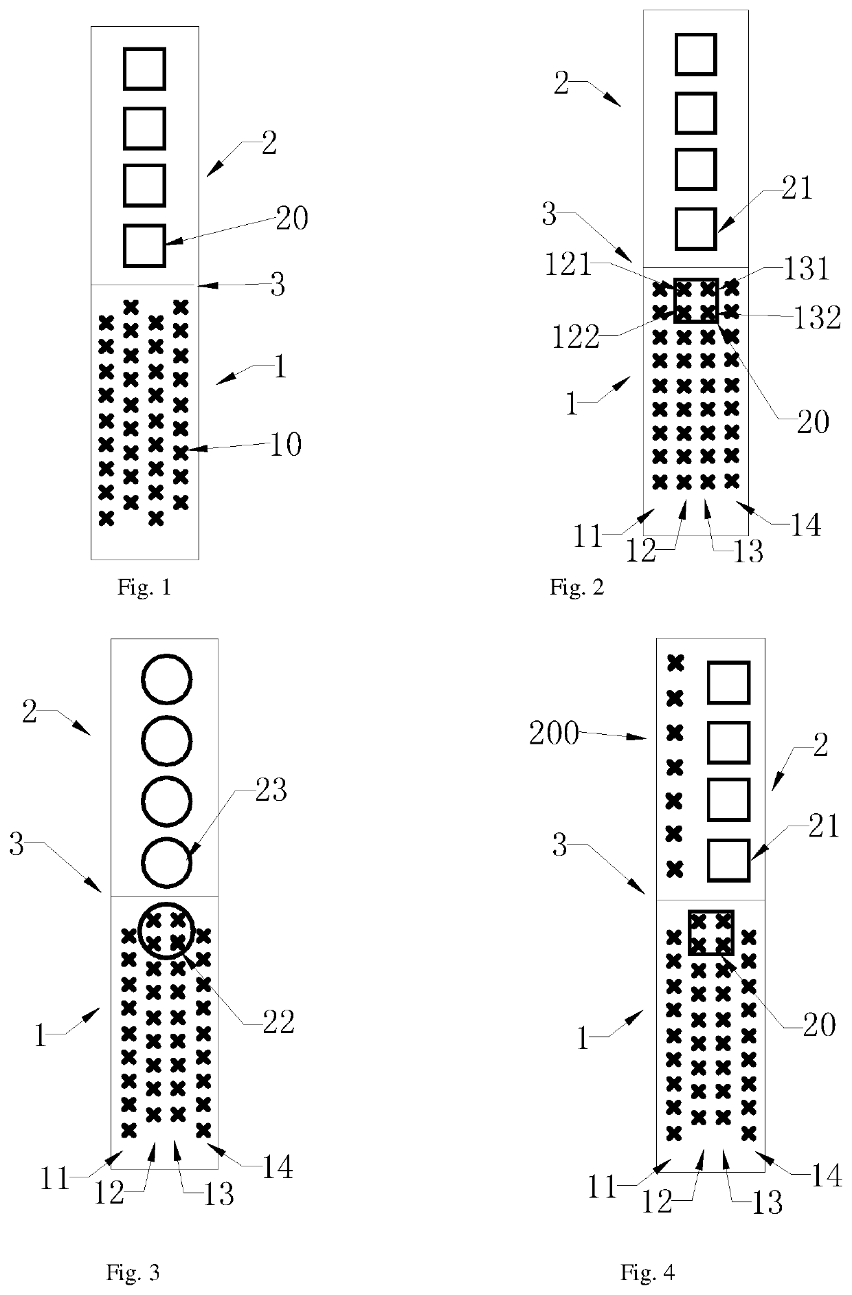
[0037]As shown in FIG. 2, the embodiment provides a multi-system integrated antenna, including a reflective plate 3, and an intelligent antenna array 1 and a base station antenna array 2 both disposed on the reflective plate 3. Wherein, the intelligent antenna array 1 and the base station antenna array 2 respectively constitute an intelligent antenna and a base station antenna, thereby realizing that an antenna of different systems (TD-LTE system and conventional cellular mobile system, such as GSM900 MHz and CDMA800 MHz) operating in different frequency bands use a common reflective plate and a radome, and realizing multi-system integrated design, which is beneficial to miniaturization of the antenna and saves installation space.

[0038]The reflective plate 3 serves as a common reflector of the intelligent antenna array 1 and the base station antenna array 2. The intelligent antenna array 1 and the base station antenna array 2 are electrically connected with the reflective plate 3, r...

embodiment 2

[0050]As shown in FIG. 3, the embodiment provides a multi-system integrated antenna, mainly characterized in that the radiation structures of the second base station antenna array element 22 and the first base station antenna array element 23 are in a ring form. The rest parts are consistent with Embodiment 1.

embodiment 3

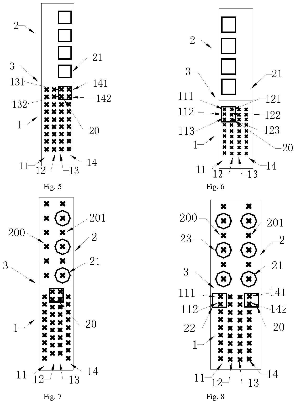
[0051]As shown in FIG. 4, the embodiment provides a multi-system integrated antenna, mainly characterized in that the base station antenna is in the form of a multi-frequency shared antenna, that is, the base station antenna array 2 further includes a plurality of high frequency base station antenna array elements 200 disposed on the same side of the reflective plate 3 with the first base station antenna array 21 (low frequency base station antenna array element), and the high frequency base station antenna array element 200 is disposed on the left side of the first base station antenna array element 21. Wherein, the first base station antenna array element 21 and the second base station antenna array element 20 operate at 880-960 MHz, and the high frequency base station antenna array element 200 operates at 1710-1880 MHz, which the two form a dual-frequency shared antenna. The intelligent antenna array operates at 1880-1920 MHz, 2010-2025 MHz, and 2575-2635 MHz. The rest parts are ...


PUM


Abstract

The present application provides a multi-system integrated antenna, including reflective plate, intelligent antenna array and base station antenna array both disposed on reflective plate. Intelligent antenna array is at lower end of reflective plate, and includes intelligent antenna subarrays each composed of plurality of intelligent antenna array elements. Base station antenna array includes first base station antenna array elements and second base station antenna array elements. First base station antenna array elements are located at upper end of reflective plate, and second base station antenna array elements are embedded in gaps of intelligent antenna array elements, and enclose intelligent antenna array elements of two adjacent intelligent antenna subarrays. Intelligent antenna array gaps are fully used by second base station antenna array element, increasing base station antenna array elements without increasing reflective plate size. Antenna gain, and facilitating antenna miniaturization is achieved.

Description

TECHNICAL FIELD[0001]The present application relates to the field of communications, and in particular, to a multi-system integrated antenna.BACKGROUND ART[0002]With increase of mobile communication network standards, multiple communication standards coexist. In order to optimize resource allocation, save station addresses and antenna feeder resources, reduce the difficulty of property coordination, and reduce investment costs, the system integrated antenna of the co-station and co-address is gradually becoming the first choice for operators to build a network.[0003]At present, the multi-system integrated antenna selected by operators usually is an effective integration of an intelligent antenna system (1880˜1920 MHz, 2010˜2025 MHz, and 2575˜2635 MHz) and a base station antenna system (880˜960 MHz and 1710˜1880 MHz) in a radome. The commonly used antenna integration method is as shown in the patent CN101465473B (shown in FIG. 1), in which the intelligent antenna array 1 and the base...

Claims


Application Information

Patent Timeline
Patent Type & Authority Applications(United States)
IPC IPC(8): H01Q1/24H01Q15/14H01Q21/06
CPCH01Q15/14H01Q21/061H01Q1/246H01Q5/42
Inventor SUN, SHANQIUWANG, QIANGLI, MINGCHAOHUANG, LIWENJIANG, WEIWEI
Owner COMBA TELECOM TECH (GUANGZHOU) CO LTD
Why Eureka
Try Eureka