Method of continuous manufacturing of solidified steelmaking slag and associated device

a technology of solidified steelmaking slag and manufacturing method, which is applied in the direction of improving process efficiency, etc., can solve the problems of increasing the cost of storage and the need for available places, affecting the use of roads, and affecting so as to increase the overall productivity of the method and shorten the treatment time

Active Publication Date: 2020-07-23
ARCELORMITTAL INVESTIGACION Y DESARROLLO SL
View PDF2 Cites 1 Cited by
  • Summary
  • Abstract
  • Description
  • Claims
  • Application Information

AI Technical Summary

Benefits of technology

[0011]The aim of the invention is to provide a continuous method of manufacturing of solidified steelmaking slag which allows stabilization of steelmaking slag while overcoming above mentioned drawbacks. An addi

Problems solved by technology

Big steelmaking plants generate hundreds of thousands of steelmaking slag per year, which generates storing costs and necessity of available place.
However, the main issue with this material comes from its significant content of free lime which ma

Method used


Image

  • Method of continuous manufacturing of solidified steelmaking slag and associated device
  • Method of continuous manufacturing of solidified steelmaking slag and associated device

Examples


first embodiment

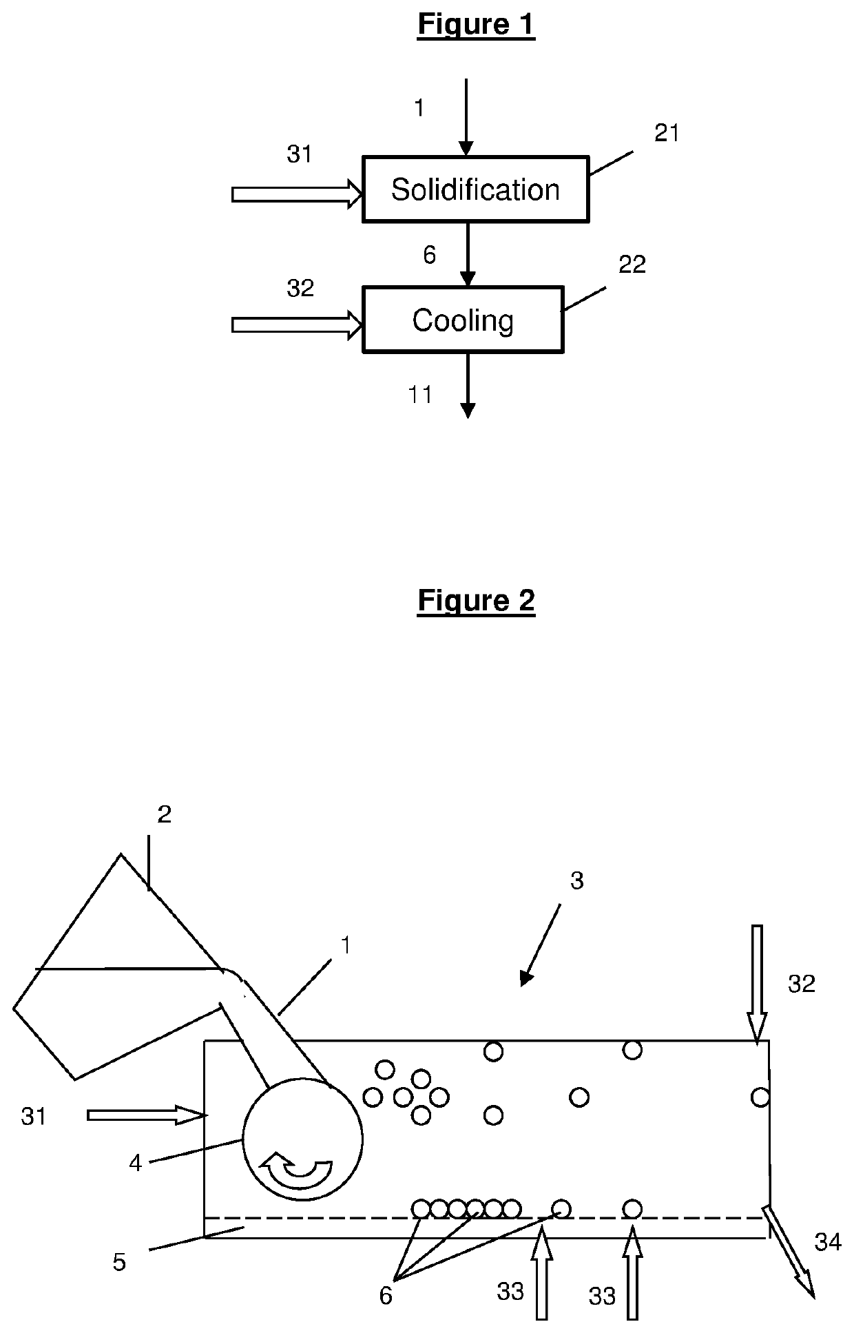
[0024]FIG. 2 illustrates an installation to perform a continuous manufacturing method according to the invention. In this installation, molten slag 1 from a steelmaking device 2 is poured into a closed chamber 3 on a granulation device 4 so as to form solidified particles of slag 6. This granulation device 4 maybe for example a rotating wheel (as illustrated). In the configuration of FIG. 2 the rotating wheel 4 is a horizontal wheel, but in another embodiment, not illustrated, it may be a vertical wheel. At the same time and is the neighboring of the slag pouring, the first carbonation gas 31 is injected through first gas injection means (not illustrated) towards the molten slag. The characteristics of this first carbonation gas 31 are the same as the ones described for the first carbonation gas 31 used in the solidification step 21 of FIG. 1. The closed chamber 3 may be insulated. The solidified slag particles 6 thus formed stay in the closed chamber 3 where they are cooled accordi...

second embodiment

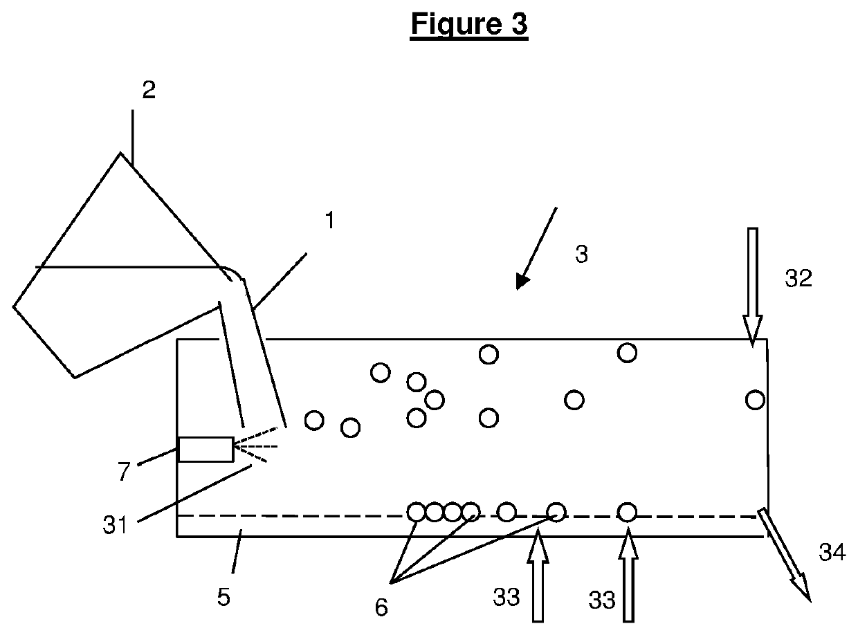
[0025]FIG. 3 illustrates an installation to perform a production method according to the invention. In this installation, molten slag 1 from a steelmaking equipment 2 is put into contact into a closed chamber 3 with a first carbonation gas 31 projected by an atomizer 7 so as to form solidified slag particles 6. The characteristics of this first carbonation gas 31 are the same as the ones described for the first carbonation gas 31 used in the solidification step 21 of FIG. 1. The atomizer 7 can be for example a SAT (Slag Atomizer Technology), developed by company Ecomaister-Hatch. The solidified slag particles 6 thus formed stay in the closed chamber 3 where they are cooled according to the cooling step 22 previously described. The closed chamber 3 comprises injection means (not illustrated) designed to inject a second carbonation gas 32 towards the solidified slag particles 6. The characteristics of this second carbonation gas 32 are the same as the ones described for the second car...


PUM

PropertyMeasurementUnit
Temperatureaaaaaaaaaa
Fractionaaaaaaaaaa

Abstract

A method of continuous manufacturing of solidified steelmaking slag including the steps of solidifying molten steelmaking slag comprising at least 2% in weight of free lime so as to produce solidified slag particles having a diameter below 1 mm, the molten steelmaking slag being put in contact with at least a first carbonation gas during such solidification, cooling the solidified slag particles down to a temperature below or equal to 300° C., in a closed chamber, the solidified slag particles being put in contact with at least one second carbonation gas during such cooling. The invention is also related to an associated device.

Description

[0001]The invention is related to a method of continuous manufacturing of steelmaking slag and to an associated device.BACKGROUND[0002]In conventional steelmaking routes, pig iron is produced into a blast furnace and is then made into steel, for example in a converter. In the converter, oxygen is blown through molten pig iron, which lowers carbon content of pig iron and changes it into steel. Mineral additions such as lime and / or dolomite are added into the converter so as to remove impurities contained in pig iron such as silicium, phosphor, and manganese and reach the required steel composition. Those additions together with the impurities extracted from pig iron form converter slags.[0003]The molten steel thus formed may then be subjected to a refining process in order to achieve steel composition requirements for high quality steel grades. Molten steel is poured in a ladle and alloying elements are added to the molten steel while impurities are removed, notably by injection of m...

Claims


Application Information

Patent Timeline
IPC IPC(8): C04B5/00C21B3/08C22B7/04
CPCC04B5/00C22B7/04C21B3/08C21B2400/026C21B2400/024C21B2400/062C21B2400/034C04B5/06C21B3/06
Inventor DE CONINCK, ERICINFANTE, IVONNEMATTOS DOS SANTOS, RAFAELOUNOUGHENE, GHANIAVAN GERVEN, THOMAS
Owner ARCELORMITTAL INVESTIGACION Y DESARROLLO SL
Why Eureka
Try Eureka