Miniaturized dual-resonance Anti-metal RFID tag

a dual-resonance, anti-metal technology, applied in the field of rfid tags, can solve the problems that the regional ceramics tags cannot completely satisfy the global requirements, and the tags cannot satisfy the requirements of hidden antennas, and achieve excellent anti-metal properties, good reading and writing performance, and great adaptability.

Active Publication Date: 2020-07-30
SHUYOU (SHANGHAI) TECH CO LTD
View PDF0 Cites 0 Cited by
  • Summary
  • Abstract
  • Description
  • Claims
  • Application Information

AI Technical Summary

Benefits of technology

[0016]The RFID tag as provided herein is able to work at two frequency bands, that is to say, it has dual-resonance. Moreover, the miniaturized dual-resonance RFID tag as provided herein contacts with the metal objects on its back surface when it needs to be adhered to the metal objects. That is to say, the side of the grounding electrode contacts with the metal objects while all of other surfaces except for the side of the grounding electrode do not contact with the metal objects. Therefore, the RFID tag as provided herein possesses good reading and writing performance, i.e., excellent anti-metal property, which can be used under metal or non-metal environments with great adaptability. In addition, utilization of the dielectric substrate with low loss and high dielectric constant, e.g., ceramic block or high frequency dielectric-slab, could reduce the size of the tag.

Problems solved by technology

However, such regional ceramics tags cannot completely satisfy the global requirements, since the miniaturized ceramics tags have narrow bandwidth, which merely satisfies one frequency band of European frequency bands (866-868 MHz) and American frequency bands (902-928 MHz).
Or the ceramics tags cover two frequency bands but have too large volume, such that the tags cannot satisfy hidden antenna requirements.

Method used


Image

  • Miniaturized dual-resonance Anti-metal RFID tag
  • Miniaturized dual-resonance Anti-metal RFID tag
  • Miniaturized dual-resonance Anti-metal RFID tag

Examples


Embodiment Construction

[0023]Several aspects of the invention are described below in details by reference to appended drawings and specific embodiments. The skilled in the art should understand that the embodiments are set forth to provide an illustration, rather than limit the scope of the present invention. The scope of the present invention is limited by the appended claims.

[0024]The terminology used herein is for the purpose of describing particular embodiments only and is not intended to be limiting of the invention. As used herein, the singular forms “a”, “an” and “the” are intended to include the plural forms as well, unless the context clearly indicates otherwise.

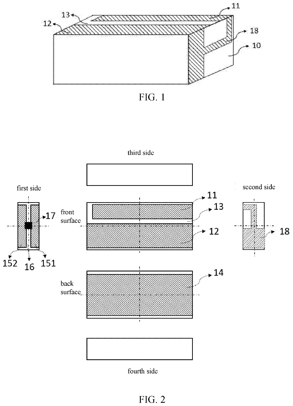
[0025]Referring to FIGS. 1 and 2, FIG. 1 is a three-dimensional structure diagram for illustrating the miniaturized dual-resonance anti-metal RFID tag according to one embodiment as described herein. FIG. 2 is a structural schematic diagram of each side of the miniaturized dual-resonance anti-metal RFID tag as shown in FIG. 1. The miniatu...


PUM

PropertyMeasurementUnit
frequencyaaaaaaaaaa
frequencyaaaaaaaaaa
dielectricaaaaaaaaaa

Abstract

Disclosed herein is a miniaturized dual-resonance anti-metal RFID tag, comprising a dielectric substrate and a microstrip antenna disposed on the surface of the dielectric substrate. The microstrip antenna comprises a first electrode and a second electrode disposed on the front surface of the dielectric substrate with a first slit disposed therebetween, a grounding electrode disposed on the back surface of the dielectric substrate, a feeding electrode disposed on the first side of the dielectric substrate and comprising a first feeding electrode and a second feeding electrode with a second slit disposed therebetween, and wherein: a driving chip is disposed at the second slit, which is coupled to the first and the second feeding electrodes respectively, the first feeding electrode is coupled to the second electrode, the second feeding electrode is coupled to the grounding electrode.

Description

CROSS-REFERENCE TO RELATED APPLICATIONS[0001]The present application is a Continuation Application of PCT application No. PCT / CN2018 / 082905 filed on Apr. 13, 2018, which claims the benefit of Chinese Patent Application No. 201711425421.9 filed on Dec. 25, 2017, the contents of the above are hereby incorporated by reference.FIELD OF THE INVENTION[0002]The present invention relates to the field of RFID tags, more particularly, to a miniaturized dual-resonance anti-metal RFID tag.BACKGROUND OF THE INVENTION[0003]RFID (Radio Frequency Identification) tags, also known as electronic tags, relate to a radio frequency identification technology, which belongs to a communication technology. With RFID tags, an identification system is able to identify specific targets, read and write related data by virtue of radio signals, without establishing mechanical or optical contact between the identification system and the specific targets. That is to say, RFID tags can be used to perform quick and ba...

Claims


Application Information

Patent Timeline
Patent Type & Authority Applications(United States)
IPC IPC(8): G06K19/077H01Q1/38H01Q5/30
CPCG06K19/0772H01Q1/38G06K19/07773H01Q5/30G06K19/07767G06K19/07771H01Q1/2225H01Q9/42H01Q5/371
Inventor ZHOU, LUTAO
Owner SHUYOU (SHANGHAI) TECH CO LTD
Why Eureka
Try Eureka