Metallic shaft

Active Publication Date: 2020-08-06
ROLLS ROYCE PLC
View PDF0 Cites 0 Cited by
  • Summary
  • Abstract
  • Description
  • Claims
  • Application Information

AI Technical Summary

Benefits of technology

[0009]A thermal barrier coating may be provided over a portion of an outer surface of the first and/or second section. The thermal barrier coating serves to slow the rate at which the portion of the section heats up and cools down, allowing the shaft to be less sensitive to temperature changes.
[0010]O

Problems solved by technology

A particular problem is where the shaft and associated

Method used


Image

  • Metallic shaft
  • Metallic shaft
  • Metallic shaft

Examples


Embodiment Construction

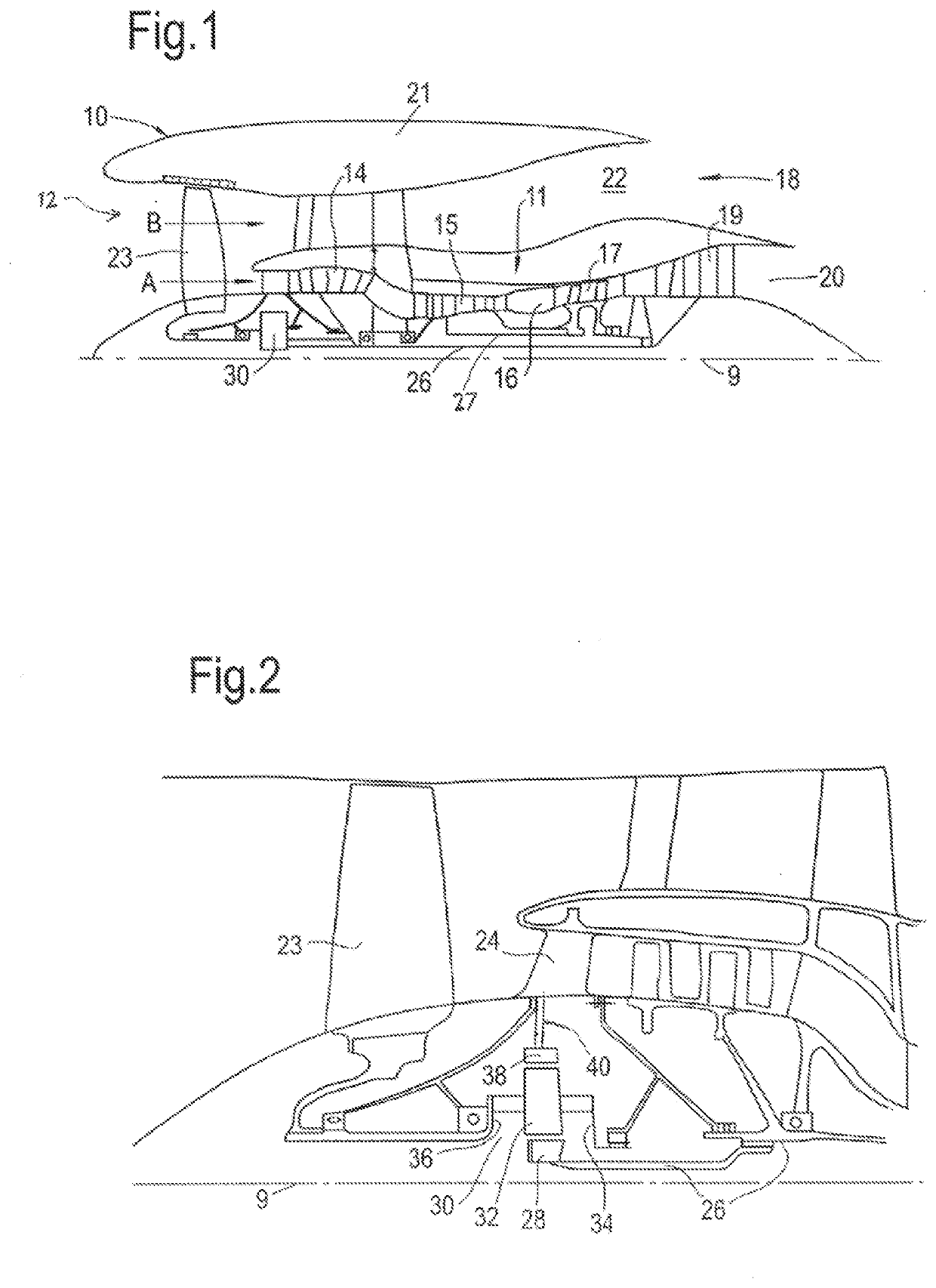
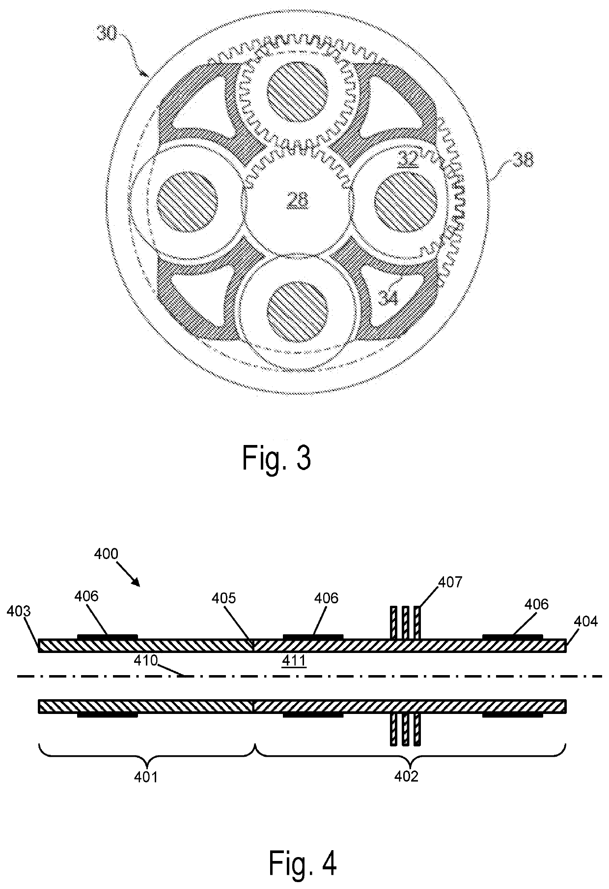
[0097]FIG. 1 illustrates a gas turbine engine 10 having a principal rotational axis 9. The engine 10 comprises an air intake 12 and a propulsive fan 23 that generates two airflows: a core airflow A and a bypass airflow B. The gas turbine engine 10 comprises a core 11 that receives the core airflow A. The engine core 11 comprises, in axial flow series, a low pressure compressor 14, a high-pressure compressor 15, combustion equipment 16, a high-pressure turbine 17, a low pressure turbine 19 and a core exhaust nozzle 20. A nacelle 21 surrounds the gas turbine engine 10 and defines a bypass duct 22 and a bypass exhaust nozzle 18. The bypass airflow B flows through the bypass duct 22. The fan 23 is attached to and driven by the low pressure turbine 19 via a shaft 26 and an epicyclic gearbox 30.

[0098]In use, the core airflow A is accelerated and compressed by the low pressure compressor 14 and directed into the high pressure compressor 15 where further compression takes place. The compres...


PUM

PropertyMeasurementUnit
Temperatureaaaaaaaaaa
Fractionaaaaaaaaaa
Fractionaaaaaaaaaa

Abstract

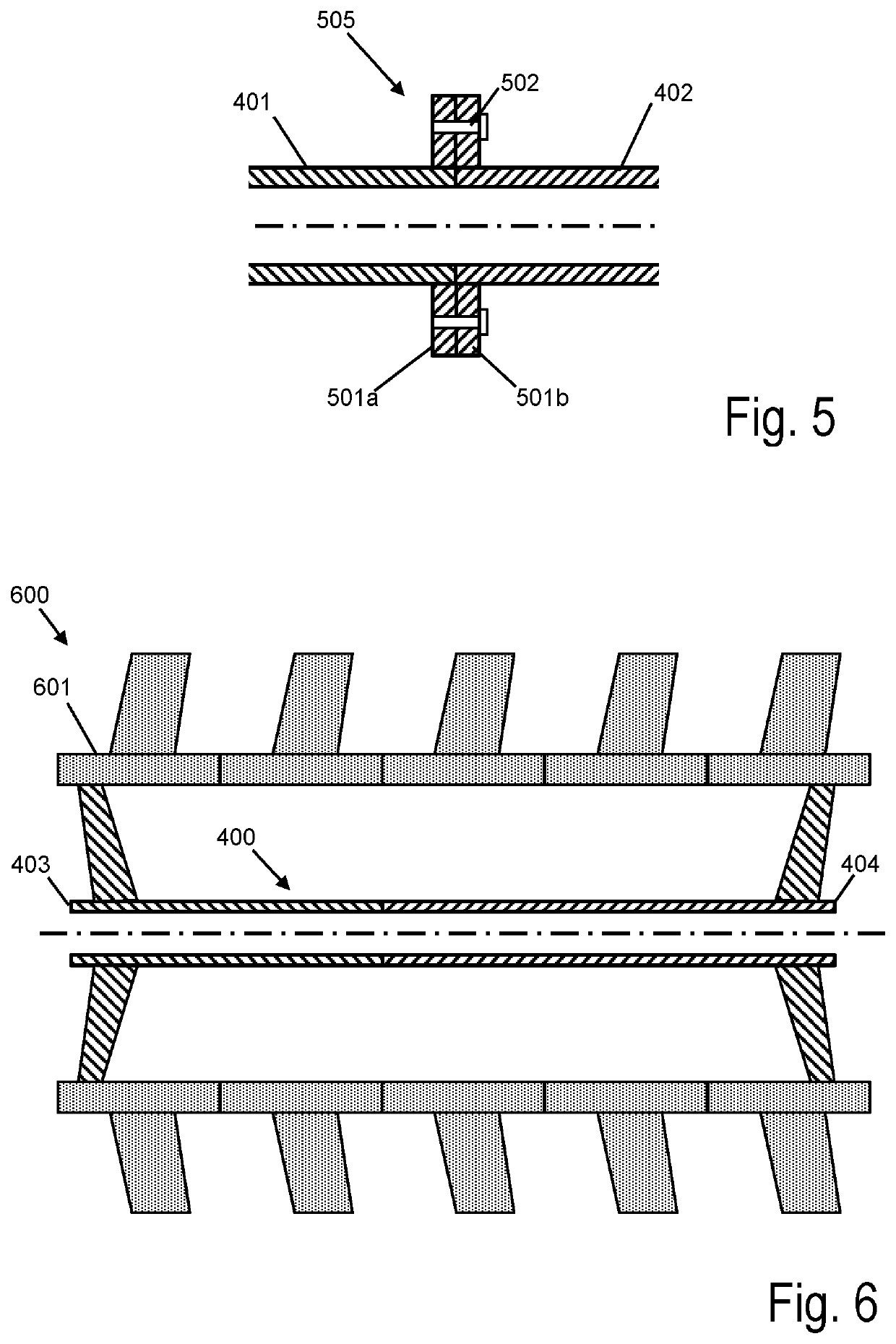
The present disclosure relates to a metallic shaft for connecting components of a gas turbine engine. Example embodiments include a metallic shaft (400) for connecting components of a gas turbine engine, the shaft (400) having a longitudinal axis (410) and comprising: a first section (401) extending from a first end (403) of the shaft (400) to a joint (405), the first section (401) composed of a material having a first thermal expansion coefficient along the longitudinal axis (410); a second section (402) extending from a second opposing end (404) of the shaft to the joint (405), the second section (402) composed of a material having a second thermal expansion coefficient along the longitudinal axis (410) that is different to the first thermal expansion coefficient.

Description

CROSS-REFERENCE TO RELATED APPLICATIONS[0001]This specification is based upon and claims the benefit of priority from UK Patent Application Number 1901557.7 filed on Feb. 5, 2019, the entire contents of which are incorporated herein by reference.BACKGROUND1. Field of the Disclosure[0002]The present disclosure relates to a metallic shaft for connecting components of a gas turbine engine.2. Description of the Related Art[0003]Metallic shafts, which may be solid or hollow (i.e. tubular), are used for various purposes in gas turbine engines, for example to mount or connect rotating components or to transport fluids such as air, oil, or mixtures thereof, between components. A particular problem is where the shaft and associated components are required to operate at high temperatures. For steel components, such operating temperatures may be from ambient temperatures up to around 400° C., whereas for titanium and nickel alloy components the operating temperatures may be higher. Thermal exp...

Claims


Application Information

Patent Timeline
IPC IPC(8): F01D5/02
CPCF01D5/025F05D2240/242F01D5/026F01D5/066F01D5/28F05D2230/23F05D2230/232F05D2230/90F05D2300/00F05D2300/171F05D2300/176Y02T50/60
Inventor ARMSTRONG, GARETH M.KEENAN, MICHAEL P.
Owner ROLLS ROYCE PLC
Why Eureka
Try Eureka