Integrated transformer with low ac losses and impedance balanced interface

Active Publication Date: 2020-08-13
ASTRONICS ADVANCED ELECTRONICS SYST
View PDF0 Cites 1 Cited by
  • Summary
  • Abstract
  • Description
  • Claims
  • Application Information

AI Technical Summary

Benefits of technology

The patent text describes a device that combines both inductive and transformer elements within the same device. This reduces conduction loss and core loss, and provides a well-defined path for leakage flux in an integrated transformer. The device also provides a balanced impedance connection with power semiconductor devices, which further reduces conduction losses and prevents current crowding in terminals. This results in a more efficient and reliable device for use in high-frequency resonant mode switching power converters.

Problems solved by technology

Yet, this system does not provide for the equal distribution of current among parallel-connected power semiconductor devices, such as field-effect transistors (FETs), diodes, or insulated-gate bipolar transistors (IGBTs), in the high current path with a balanced impedance interconnect to the high current winding.
Further, the configuration of these power semiconductor devices, such as metal-oxide-semiconductor field-effect transistors (MOSFETS), diodes, or IGBTS, as disclosed, fails to complete a winding turn, and therefore results in increased loss.
Moreover, an additional deficiency of such transformers is the inability to achieve sufficiently high leakage inductance, suitably high for a resonant converter to operate over a wide input voltage range, without inserting a large gap between the primary and secondary windings.
However large gaps between the primary and secondary windings are undesirable, as they result in substantially elevated AC losses in the windings.
Yet, this results in very high AC conduction losses, since the first and secondary windings are not overlapping.
The separation of cores results in non-shared flux or conduction paths, contributing to the higher losses.
Even in instances where the inductive element and the transformer are integrated into the same core, as shown in U.S. Pat. No. 6,714,428, titled “Combined Transformer-inductor Device for Application to DC-to-DC Converter with Synchronous Rectifier” by Guisong Huang et al., the electrical separation of the inductive element and the transformer still fails to yield a useful resonant converter.
Indeed, even when the same core is utilized for the inductive element and the transformer, separation of the primary and secondary windings causes elevated AC conduction loss, as shown in U.S. Pat. No. 5,783,984, titled “Method and Means for Combining a Transformer and Inductor on a Single Core Structure” by Carl Keuneke.
U.S. Pat. No. 4,613,841, titled “Integrated Transformer and Inductor” by Victor Roberts, showcases the problem of separating the primary and secondary windings by even a portion of the core, within the same core, resulting in elevated AC losses.
Further, the separation in this instance prevents the provision of a balanced impedance interconnect between a high current winding and parallel-connected power semiconductor devices.

Method used


Image

  • Integrated transformer with low ac losses and impedance balanced interface
  • Integrated transformer with low ac losses and impedance balanced interface
  • Integrated transformer with low ac losses and impedance balanced interface

Examples


Embodiment Construction

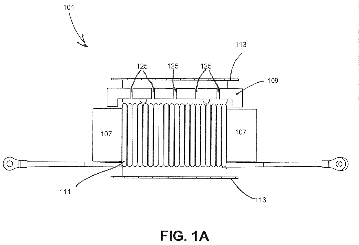
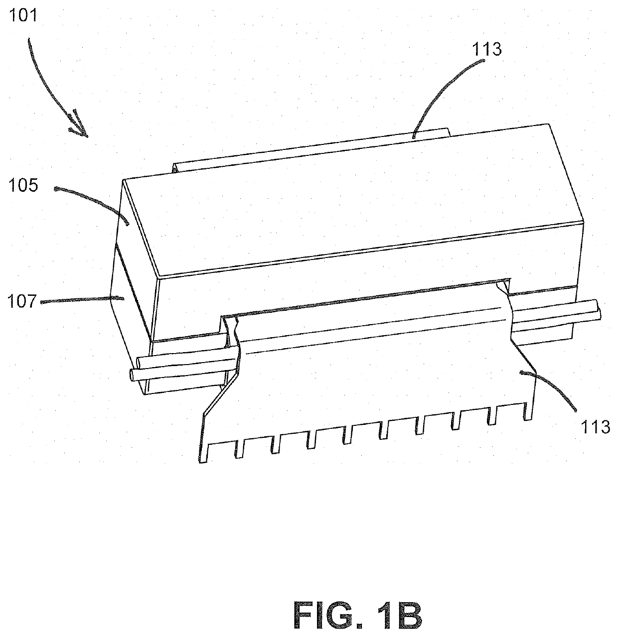
[0026]An exemplary embodiment is described herein with reference to the system depicted in FIGS. 1A and 1B. The transformer 101 includes a core formed of three sections: top core 105, bottom core 107 and shunt core 109, with shunt core 109 containing an array of distributed gaps 125.

[0027]In an embodiment, transformer 101 may be a 7 kW rated transformer. However, it should be noted that transformer 101 may be rated for any other suitable high-current or high-power transformers. For example, high current may be in the tens of amperes to thousands of amperes, or any other suitable amount. In a further example, high power may be in the hundreds of watts to hundreds of thousands of watts.

[0028]In accordance with an embodiment, shunt core 109 may be formed of a low-permeability magnetic material, such as powdered metal. However, the shunt core 109 may also be formed as a segmented core of a higher-permeability material like ferrite. The choice of shunt core material will depend on variou...


PUM


Abstract

An integrated transformer device is provided with both inductive and transformer elements. The inductive and transformer elements are combined within the same device, sharing at least a part of the same magnetic and electrical paths. The integrated transformer device comprises a top core, a bottom core, and a shunt core. A high voltage winding is wound around the bottom core. A low voltage winding is wound around the bottom core and the shunt core. Power semiconductor devices, connected in parallel, form a portion of the low voltage winding and are disposed at a location proximate to the high voltage winding.

Description

CROSS REFERENCE TO RELATED APPLICATION[0001]The present non-provisional application claims priority to provisional application Ser. No. 62 / 805,289 filed Feb. 13, 2019, also entitled “Integrated Transformer with Low AC Losses and Impedance Balanced Interface,” the disclosure of which is incorporated herein by reference.FIELD OF THE DISCLOSURE[0002]The present disclosure generally relates to a transformer, and more particularly, to an integrated transformer with low alternating current (AC) power loss.BACKGROUND OF THE DISCLOSURE[0003]Converters are devices that convert electrical energy from one form to another and are typically used to convert one voltage to another voltage. Resonant converters and resonant transition converters rely on either a series inductive component or a transformer-integrated inductor to provide inductance, which together with and added capacitance, creates a resonant tank. These resonant and resonant transition converters utilize the resonant tank and soft s...

Claims


Application Information

Patent Timeline
IPC IPC(8): H01F27/38H01F27/24H01F27/42H01F27/06H01F27/28H01F3/14H01F30/06H05K1/16H05K1/18
CPCH01F2027/065H05K1/165H01F27/06H01F27/425H01F27/38H01F27/24H05K2201/1003H05K1/181H01F3/14H01F27/2804H01F30/06H01F3/12H01F27/2866H01F27/29H05K1/182H01F38/08Y02B70/10
Inventor WAMBSGANSS, WARREN J.
Owner ASTRONICS ADVANCED ELECTRONICS SYST
Why Eureka
Try Eureka