Transducer for ultrasonic scalpel

a transducer and ultrasonic technology, applied in the field of medical devices, can solve problems such as reducing system stability, and achieve the effect of sacrificing stability and improving the gain of the ultrasonic scalpel system

Pending Publication Date: 2020-09-03
INNOLCON MEDICAL TECH SUZHOU
View PDF6 Cites 4 Cited by
  • Summary
  • Abstract
  • Description
  • Claims
  • Application Information

AI Technical Summary

Benefits of technology

[0005]Provided is a transducer that improves the gain of the ultrasonic scalpel system but without sacrificing the stability.

Problems solved by technology

However, too much high gain will reduce the stability of the system.

Method used


Image

  • Transducer for ultrasonic scalpel
  • Transducer for ultrasonic scalpel

Examples


Embodiment Construction

[0029]In order to enable those skilled in the art to better understand the technical schemes of the present invention, the present invention will be further described in detail below with reference to specific embodiments.

[0030]In order to meet the appropriate gain, dielectric performance, enough ability to drive tissue cutting and coagulating, and the requirements from circuit drive, the present invention proposes the following design scheme:

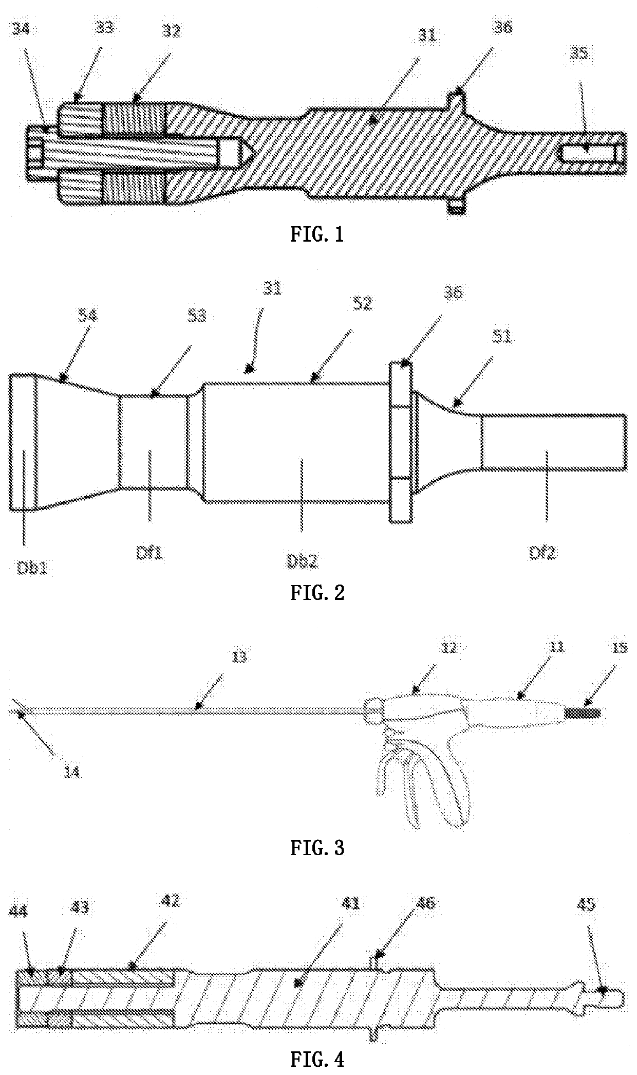
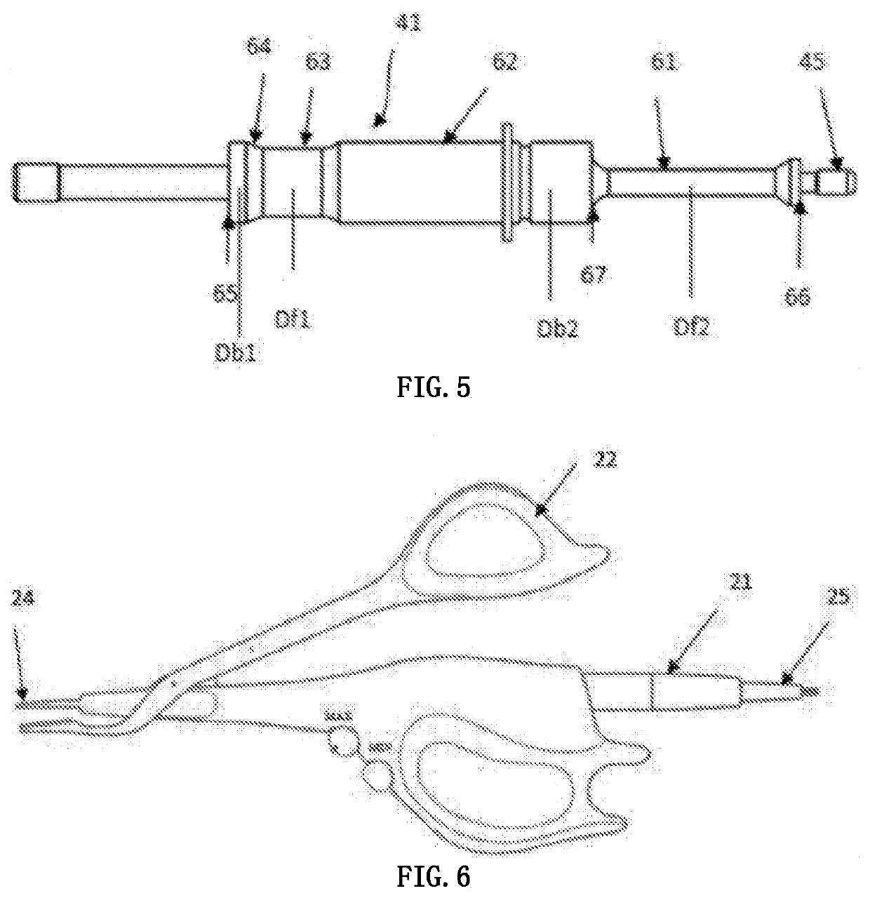
[0031]A transducer used for an ultrasonic scalpel, which from distal end to proximal end comprises a connecting feature, a fixing feature, a horn, a piezoelectric converting body, a rear-end ring and a connecting member. The total length of the converting body is Ld, and its wavelength corresponding to the operating frequency of the transducer is λ. The horn is provided with two sections for amplitude amplification; the diameters of the front and back ends at the two sections are Df1, Db1 and Df2, Db2; the following conditions are satisfied bet...


PUM


Abstract

A transducer for an ultrasonic scalpel, which comprises, from distal end to proximal end of a connecting feature, a fixing feature, a horn, a piezoelectric converting body, a rear-end ring, and a connecting member. By following a design principle of constraints in the parameter relationships between the piezoelectric converting body and the horn in the transducer, a transducer having both appropriate gain and stable performance can be achieved.

Description

BACKGROUNDTechnical Field[0001]This invention relates to the field of medical devices, in particular to an ultrasonic scalpel transducer.Description of the Related Art[0002]Ultrasonic scalpel large-scale applications have had more than 20 years of history. Comparing to other surgical methods, ultrasonic scalpel has advantages of producing less smoke, clearer surgical view field, smaller thermal damage; it combines multiple functions of tissue cutting, coagulation and dissection in one instrument, and is able to precisely control the cutting and coagulation area; no electrical damage; rapid ultrasonic oscillation has a self-cleaning effect, which reduces the sticking of blade with tissue.[0003]Ultrasonic scalpel can be used for laparoscopic and endoscopic surgery, and for open surgery as well; can be used in combination with other surgical instruments, such as traditional mechanical scalpels and electric knifes, and can be used alone as well, because it combines multifunction of gras...

Claims


Application Information

Patent Timeline
Patent Type & Authority Applications(United States)
IPC IPC(8): A61B17/32B06B1/06H02N2/00H04R17/00
CPCA61B2017/320075A61B17/320068H02N2/0025B06B1/06H04R17/005A61B2017/22018B06B3/00A61B17/2812A61B17/320092A61B17/3211A61B2017/00402B06B2201/76
Inventor YAN, ZHONGYUWANG, LEILUO, WEI
Owner INNOLCON MEDICAL TECH SUZHOU
Why Eureka
Try Eureka