Supercharge Your Innovation With Domain-Expert AI Agents!

Selective distillation apparatus and distillation method

a distillation apparatus and distillation method technology, applied in the direction of chemistry apparatus and processes, separation processes, thermal naphtha reforming, etc., can solve the problems of limitation that cannot but have a processing capacity as much, and achieve high-efficiency operation, improved thermodynamic efficiency, and increased throughput of the distillation column

Active Publication Date: 2020-09-03
LG CHEM LTD
View PDF13 Cites 0 Cited by
  • Summary
  • Abstract
  • Description
  • Claims
  • Application Information

AI Technical Summary

Benefits of technology

The present patent describes a selective distillation apparatus that can improve thermodynamic efficiency and increase throughput by switching between serial and parallel connection modes. This allows for high-efficiency and high-capacity operation without shutting down the apparatus. The technical effect of this invention is to enhance the efficiency and productivity of distillation processes.

Problems solved by technology

When the distillation columns are connected in series and run as in FIG. 1, the same effect as operating the distillation column having high number of stages can be obtained, but there is a limitation that cannot but have a processing capacity as much as one tower using two towers.

Method used


Image

  • Selective distillation apparatus and distillation method
  • Selective distillation apparatus and distillation method
  • Selective distillation apparatus and distillation method

Examples


example 2

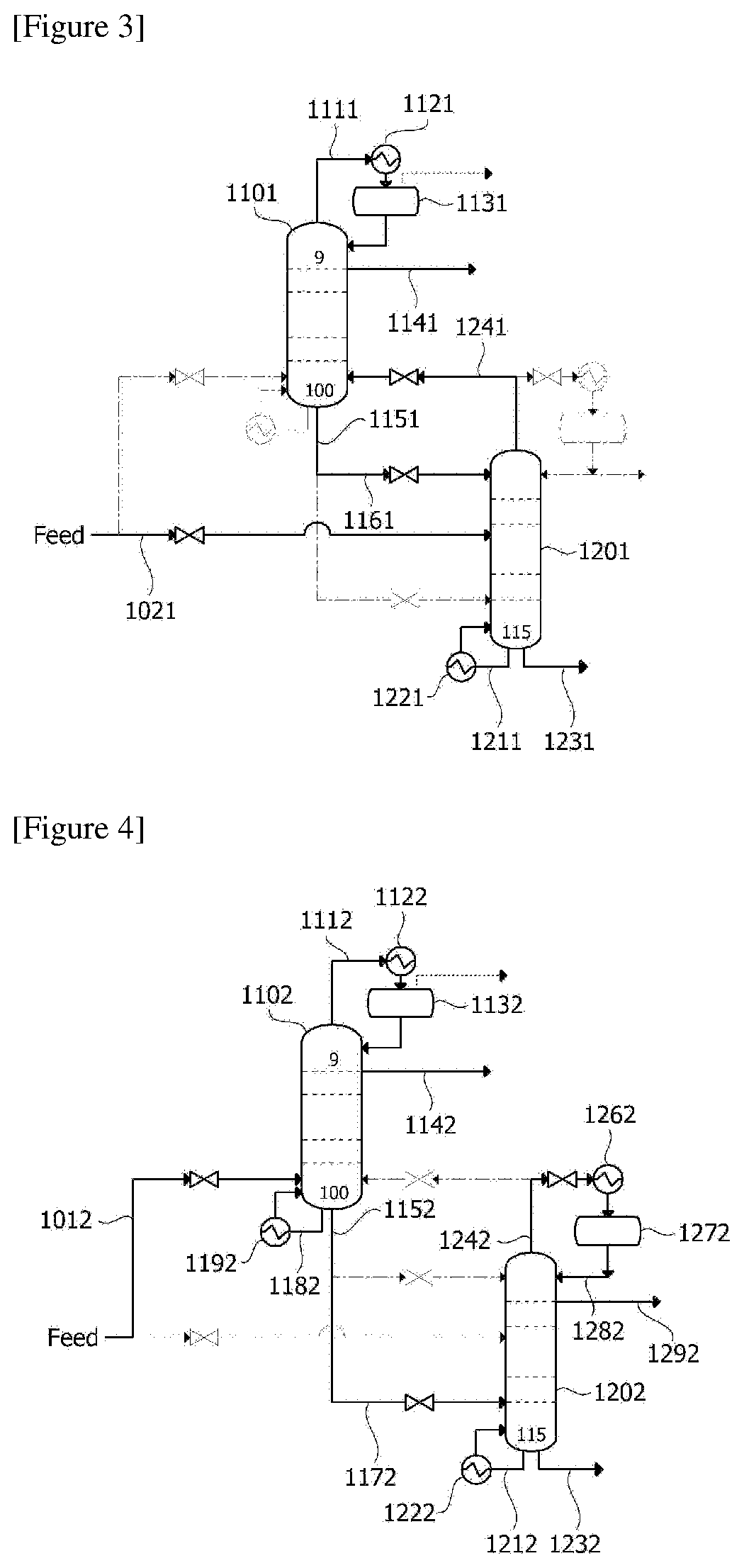
[0063]As illustrated in FIG. 4, in the parallel connection mode, the first supply line (1012), the first connecting line (1152+1172) connecting the bottom outlet of the first distillation column (1102) and the lower inlet of the second distillation column (1202), and the first discharge line (1142) connected to the upper outlet of the first distillation column (1102) were activated, the top outlet of the first distillation column (1102) was connected to the top reflux device (1132) of the first distillation column (1102), and the top reflux device (1132) of the first distillation column (1102) was connected to the upper inlet of the first distillation column (1102). The bottom outlet of the second distillation column (1202) was connected to the bottom reboiler (1222) of the second distillation column (1202) and the bottom reboiler (1222) of the second distillation column (1202) was connected to the lower inlet of the second distillation column (1202). The top reflux device (1132) an...

example 3

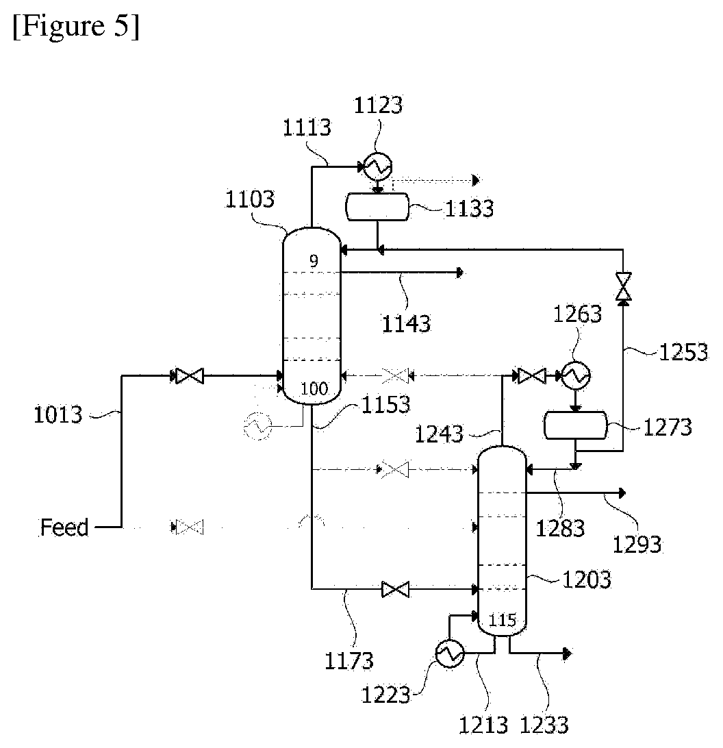
[0065]As illustrated in FIG. 5, the same device configuration as in Example 2 was used except that in the parallel connection mode, the fourth connecting line (1313+1323) connecting the upper inlet of the first distillation column (1103) and the top outlet of the second distillation column (1203) was activated and the bottom reboiler (1193) of the first distillation column (1103) was inactivated. Ethylene and ethane were separated in the same manner as in Example 2 except that all the bottom condensate of the first distillation column (1103) was introduced into the second distillation column (1203) through the first connecting line (1153+1173) and a stream of 5 kg / hr in the outflow stream of the top reflux device (1273) of the second distillation column (1203) was introduced into the first distillation column (1103) through the fourth connecting line (1313+1323) and the energy supply quantity through the bottom reboiler of the second distillation column was 15.72 Gcal / hr.

TABLE 112-1...


PUM


Abstract

The present application relates to a selective distillation apparatus and a distillation method, which provides a distillation apparatus capable of switching between a serial connection mode and a parallel connection mode on the situation, thereby enabling selective operation of high-efficiency operation and high-capacity operation.

Description

TECHNICAL FIELD[0001]The present invention relates to a selective distillation apparatus capable of switching between high-efficiency operation and high-capacity operation to each other using two distillation columns and a distillation method using the selective distillation apparatus. The present application claims the benefit of priority based on Korean Patent Application No. 10-2016-0118045 filed on Sep. 13, 2016, the disclosure of which is incorporated herein by reference in its entirety.BACKGROUND ART[0002]Various raw materials such as crude oil are usually a mixture of many chemical substances in many cases, where the mixture is rarely used in the industry as such and usually used after being separated into each compound. A typical chemical process for separating the mixture is a distillation process.[0003]In general, the distillation process evaporates and separates the mixed materials of a binary system or more present in the feedstock by the difference in boiling points. As...

Claims


Application Information

Patent Timeline
IPC IPC(8): B01D3/42C07C7/04B01D3/14B01D3/32B01D3/00
CPCB01D3/008B01D3/143B01D3/4255C07C7/04B01D3/4205B01D3/322B01D3/14C10G35/02C10G35/24C10G2300/1044
Inventor KIM, TAE WOOLEE, SUNG KYUKIM, SUNG KYUNSHIN, JOON HOCHOO, YEON UK
Owner LG CHEM LTD
Features
  • R&D
  • Intellectual Property
  • Life Sciences
  • Materials
  • Tech Scout
  • Unparalleled Data Quality
  • Higher Quality Content
  • 60% Fewer Hallucinations
Learn More