Method of Removing a Ceramic Coating from a Ceramic Coated Metallic Article

Pending Publication Date: 2020-09-17
ROLLS ROYCE PLC
View PDF9 Cites 0 Cited by
  • Summary
  • Abstract
  • Description
  • Claims
  • Application Information

AI Technical Summary

Benefits of technology

The patent describes a process that allows a caustic solution to penetrate through a ceramic coating without causing significant damage to the coating. This results in a weaker layer of oxide between the coating and a metallic surface, which can be useful in some applications.

Problems solved by technology

During the manufacture of ceramic coated metal articles occasionally defects are produced in the ceramic coating resulting in a ceramic coated metal article not falling within acceptable standards for its intended use.
These defects may be one or more of lack of coating, thicker coating than required, chipped coating, pits and spits, delamination, staining, contamination and overspray.
After a period of operation of a ceramic coated article the ceramic coating may become damaged, e.g. part of the ceramic coating have spalled off, and again is not of acceptable standards for its intended use.
However, these processes do not produce satisfactory results in that they do not fully remove all of the ceramic coating and / or they remove some or all of the metallic bond coating.
We have found that the use of a caustic solution is effective in permeating through a ceramic coating with a columnar grain microstructure to weaken an oxide layer between the metallic bond coating and the columnar grain ceramic coating, but the caustic solution is totally ineffective in permeating through a ceramic coating with a lamellae microstructure.
We have found that the use of conventional water jet blasting is ineffective in the removal of a ceramic coating with a columnar grain microstructure from the convex side of metallic articles as well as from the inside of cooling apertures and complete removal of the ceramic coating is only possible with repeated water jet blasting but this removes the metallic bond coating or erodes the metallic bond coating and reduces the surface roughness of the metallic bond coating.
Applying a thin metallic bond coating layer may result in an overall metallic bond coating which has regions which are deficient of desirable elements, such as aluminum, which is required to form an alumina layer on the metallic bond coating and between the metallic bond coating and the ceramic coating as well as adding expense.
If the metallic bond coating is completely removed it is necessary to apply a full thickness metallic bond coating which adds even more expense.

Method used


Image

  • Method of Removing a Ceramic Coating from a Ceramic Coated Metallic Article
  • Method of Removing a Ceramic Coating from a Ceramic Coated Metallic Article
  • Method of Removing a Ceramic Coating from a Ceramic Coated Metallic Article

Examples


Embodiment Construction

[0092]Aspects and embodiments of the present disclosure will now be discussed with reference to the accompanying figures. Further aspects and embodiments will be apparent to those skilled in the art.

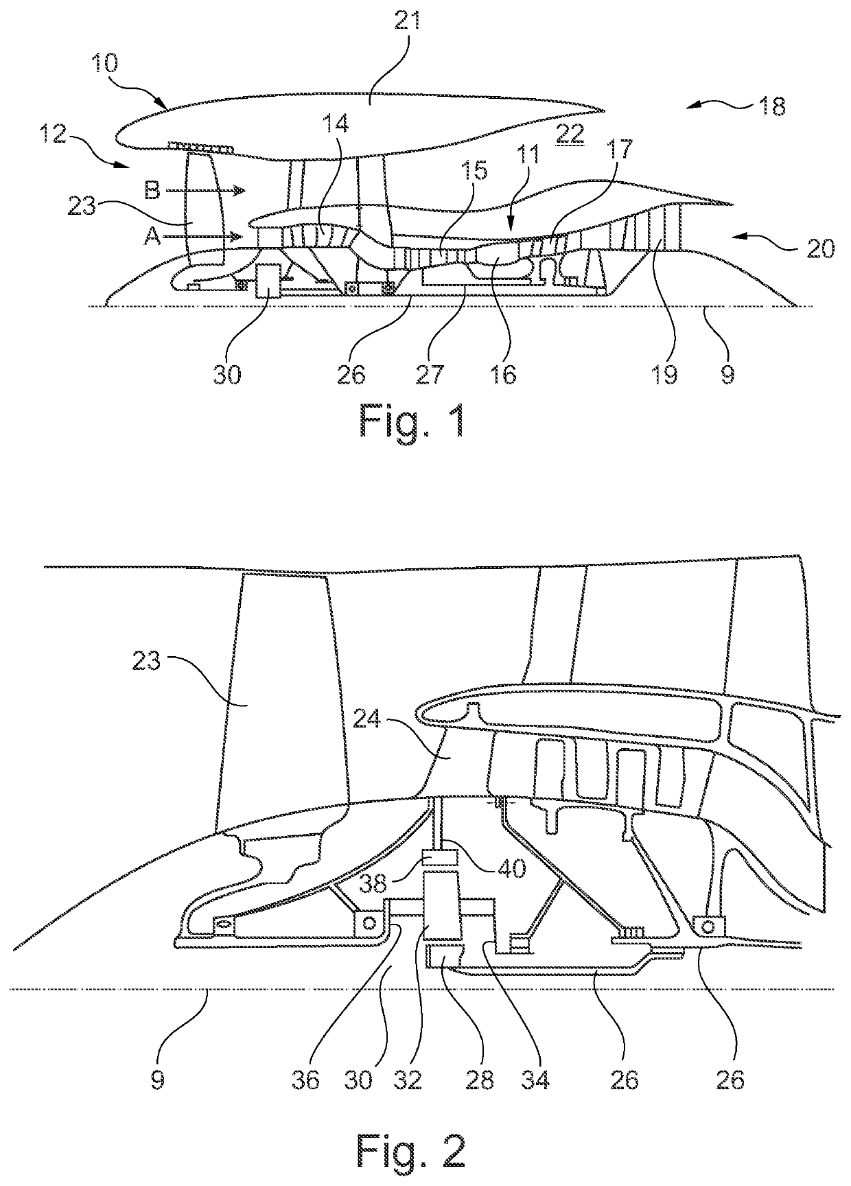
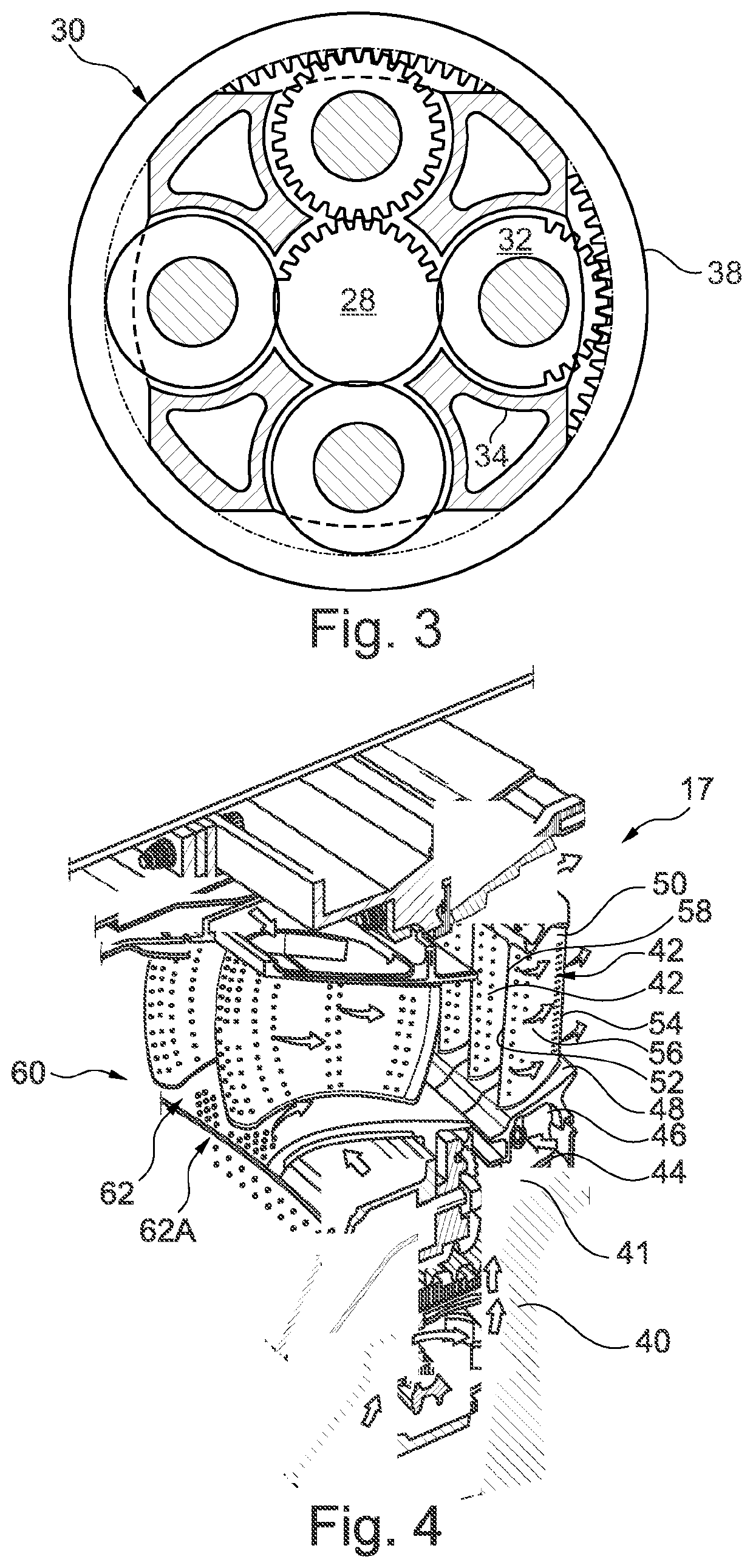
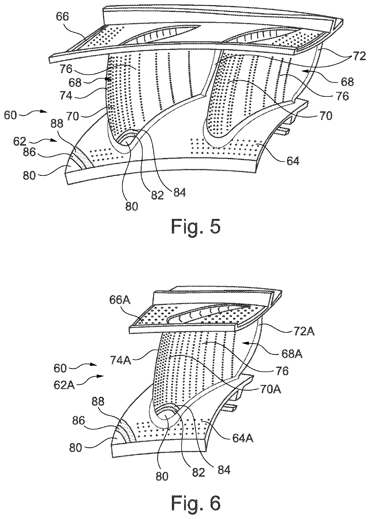
[0093]FIG. 1 illustrates a gas turbine engine 10 having a principal rotational axis 9. The engine 10 comprises an air intake 12 and a propulsive fan 23 that generates two airflows: a core airflow A and a bypass airflow B. The gas turbine engine 10 comprises a core 11 that receives the core airflow A. The engine core 11 comprises, in axial flow series, a low pressure compressor 14, a high-pressure compressor 15, combustion equipment 16, a high-pressure turbine 17, a low pressure turbine 19 and a core exhaust nozzle 20. A nacelle 21 surrounds the gas turbine engine 10 and defines a bypass duct 22 and a bypass exhaust nozzle 18. The bypass airflow B flows through the bypass duct 22. The fan 23 is attached to and driven by the low pressure turbine 19 via a shaft 26 and an epicyclic gearbox 3...


PUM

PropertyMeasurementUnit
Temperatureaaaaaaaaaa
Lengthaaaaaaaaaa

Abstract

A method of removing a ceramic coating from a ceramic coated metallic article without damaging the metallic bond coating, the metallic article having a first and second portions, each of the portions comprising a metallic bond coating and a ceramic coating on the metallic bond coating, the ceramic coating on the second portion being less porous than the ceramic coating on the first portion. The method comprises the steps of a) immersing the ceramic coated metallic article in a caustic solution; b) maintaining the ceramic coated metallic article in the caustic solution at atmospheric pressure for a predetermined time period and at a predetermined temperature; c) removing the ceramic coated metallic article from the caustic solution; d) rinsing the ceramic coated metallic article in water at ambient temperature; e) water jet blasting the first portion of the metallic article to remove the ceramic coating; and f) water jet blasting the second portion of the metallic article to remove the ceramic coating.

Description

CROSS-REFERENCE TO RELATED APPLICATIONS[0001]This specification is based upon and claims the benefit of priority from United Kingdom patent application number GB 1903484.2 filed on Mar. 14th 2019, the entire contents of which are incorporated herein by reference.BACKGROUNDTechnical Field[0002]The present disclosure relates to a method of removing a ceramic coating from a ceramic coated metallic article and in particular relates to a method of removing a ceramic coating from a thermal barrier coated metallic article, e.g. a superalloy article.Description of the Related Art[0003]Internal combustion engines for example continuous combustion engine e.g. gas turbine engines, reciprocating engines e.g. diesel engines and petrol engines and rotary engines e.g. Wankel engines and turbomachines have thermal barrier coated metallic articles, e.g. ceramic coated metallic articles. Gas turbine engines have ceramic coated turbine blades, turbine vanes, combustion chamber tiles, combustion chambe...

Claims


Application Information

Patent Timeline
IPC IPC(8): C23G1/14B08B3/02B24C5/04B24C7/00F01D5/28
CPCB24C5/04C23G1/14F05D2300/611F01D5/288F05D2230/90B08B3/024F05D2230/10B24C7/0076F01D5/005F05D2230/80F05D2300/20C23G5/00C23G1/19
Inventor DELFAN-AZARI, MEHRZAD
Owner ROLLS ROYCE PLC
Why Eureka
Try Eureka