Louver film, planar light source device, and liquid crystal display device

a liquid crystal display and light source technology, applied in lighting and heating devices, instruments, electric lighting, etc., can solve the problems of low light use efficiency and image darkening, and achieve the effect of improving light use efficiency and directivity for visibility

Inactive Publication Date: 2020-09-17
FUJIFILM CORP
View PDF0 Cites 3 Cited by
  • Summary
  • Abstract
  • Description
  • Claims
  • Application Information

AI Technical Summary

Benefits of technology

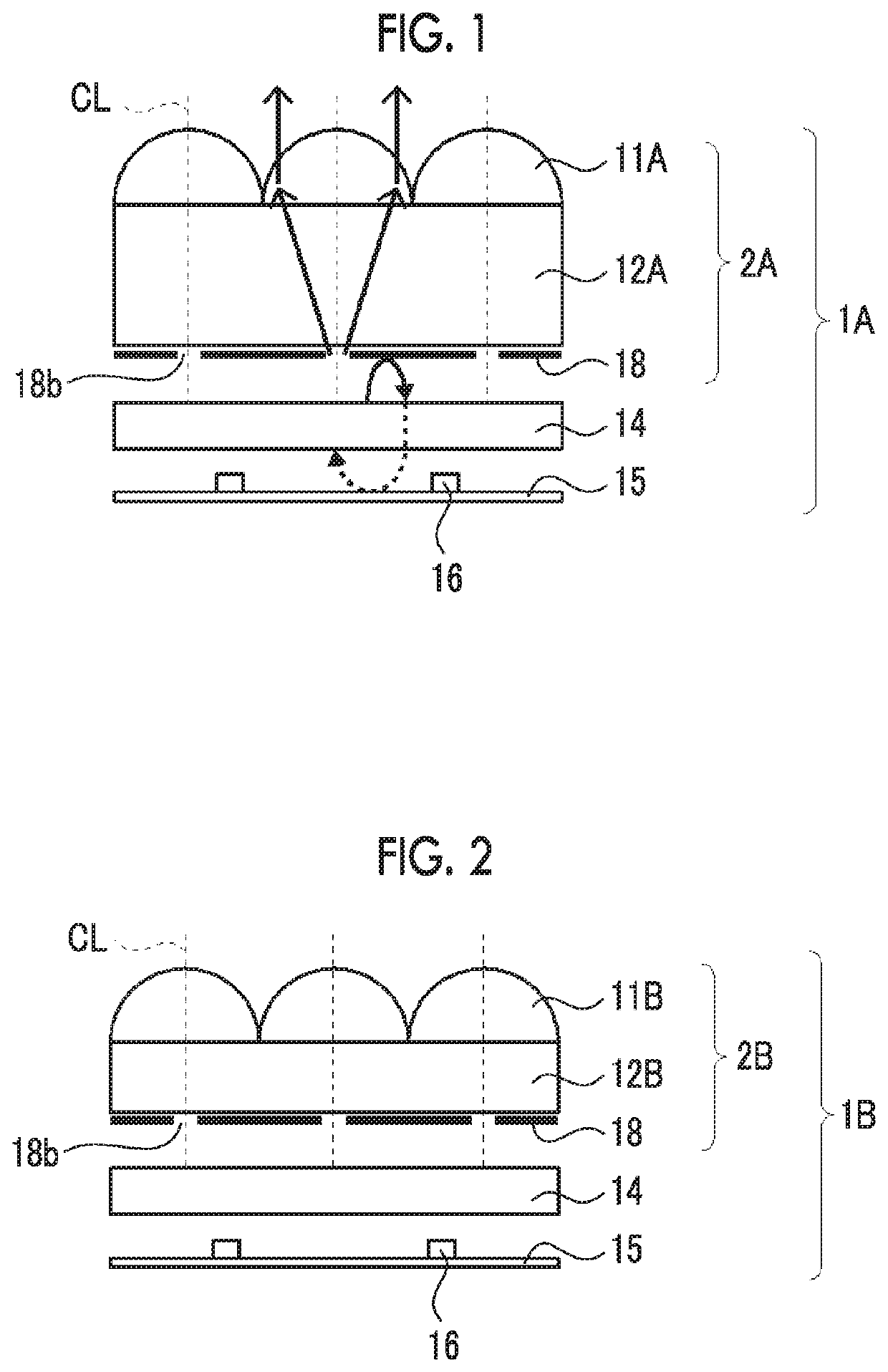
[0009]Therefore, an object of the present invention is to provide a louver film, a planar light source device, and a liquid crystal display device in which the directivity for visibility has been further improved while light use efficiency is maintained.
[0012]Here, the louver film is a film having improved directivity. Further, in a liquid crystal display device comprising a planar light source device that includes the film, the louver film is a film in which the directivity for visibility is improved as compared with a case where the film is not provided so that visual recognition, for example, in an oblique direction can be suppressed. In addition, the louver film is a film in which the viewing angle is limited and projection of an image in a region where the image is not intended to be displayed is improved.
[0018]Further, in the planar light source device, the brightness (Y0) measured for every degree from a polar angle of 0° (front direction) to a polar angle of 88° is obtained using a measuring device “EZ-Contrast XL88” (manufactured by ELDIM Co., Ltd.), and the ratio between the brightness value in the front direction and the minimum brightness value at a polar angle of 60° is calculated as an SN ratio (=brightness in front direction / minimum brightness value at polar angle of 60°). The S / N ratio is evaluated as skirting. As the SN ratio increases, the skirting becomes improved so that the directivity becomes higher.
[0030]According to the present invention, it is possible to provide a louver film which enables further improvement of directivity for visibility while light use efficiency is maintained, and a planar light source device and a liquid crystal display device which comprise the louver film.

Problems solved by technology

However, since the light use efficiency is low and the brightness of a display image becomes lower in the louver film of JP4856806B, the image is darkened.

Method used


Image

  • Louver film, planar light source device, and liquid crystal display device
  • Louver film, planar light source device, and liquid crystal display device
  • Louver film, planar light source device, and liquid crystal display device

Examples


example 1

[0291]In Example 1, a polyethylene terephthalate film (trade name: COSMOSHINE (registered trademark) A4300, manufactured by Toyobo Co., Ltd., thickness of 125 μm, refractive index of 1.57) was prepared as a first support. The surface of the first support was coated, using a bar coater, with a titanium oxide particle-containing polymerizable composition (composition type 2) prepared to have a refractive index of 1.55 according to the following item 1, the support was exposed at 5 J / cm2 so that the composition was cured in a nitrogen atmosphere using a UV exposure machine (EXECURE 3000W, manufactured by HOYA CANDEO OPTRONICS Corp.) while an uneven roller having a surface shape inverted from the shape to be formed was pressed so that each convex arc (lens) whose cross section had a curvature radius of 57 μm was formed on the surface at a pitch of 100 μm, and the support was peeled off from the uneven roller to prepare an uneven shape on the surface.

[0292]Thereafter, the surface of the ...

example 2

[0304]In Example 2, a polyethylene terephthalate film (trade name: COSMOSHINE (registered trademark) A4300, manufactured by Toyobo Co., Ltd., thickness of 125 Gm, refractive index of 1.57) was prepared as a first support. The surface of the first support was coated, using a bar coater, with a titanium oxide particle-containing polymerizable composition (composition type 2) prepared to have a refractive index of 1.55 according to the above-described item 1, the support was exposed at an irradiation dose of 5 J / cm2 so that the composition was cured in a nitrogen atmosphere using a UV exposure machine (EXECURE 3000W, manufactured by HOYA CANDEO OPTRONICS Corp.) while an uneven roller having a surface shape inverted from the shape to be formed was pressed so that each convex arc (lens) whose cross section had a curvature radius of 57 μm was formed on the surface at a pitch of 100 μm, and the support was peeled off from the uneven roller to prepare an uneven shape on the surface.

[0305]Th...

example 3

[0306]In Example 3, a polyethylene terephthalate film (trade name: COSMOSHINE (registered trademark) A4300, manufactured by Toyobo Co., Ltd., thickness of 75 μm, refractive index of 1.57) was prepared as a first support. The surface of the first support was coated, using a bar coater, with a titanium oxide particle-containing polymerizable composition (composition type 2) prepared to have a refractive index of 1.69 according to the above-described item 1, the support was exposed at an irradiation does of 5 J / cm2 so that the composition was cured in a nitrogen atmosphere using a UV exposure machine (EXECURE 3000W, manufactured by HOYA CANDEO OPTRONICS Corp.) while an uneven roller having a surface shape inverted from the shape to be formed was pressed so that each convex arc (lens) whose cross section had a curvature radius of 50 μm was formed on the surface at a pitch of 100 μm, and the support was peeled off from the uneven roller to prepare an uneven shape on the surface.

[0307]The...


PUM

PropertyMeasurementUnit
refractive indexaaaaaaaaaa

Abstract

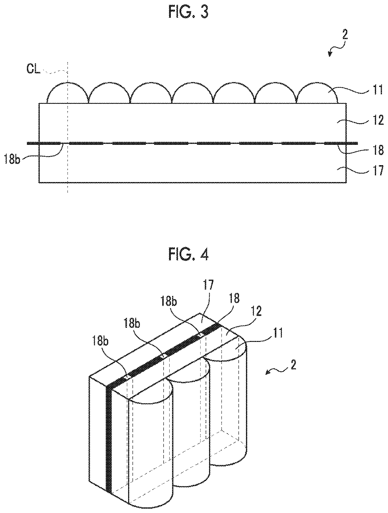
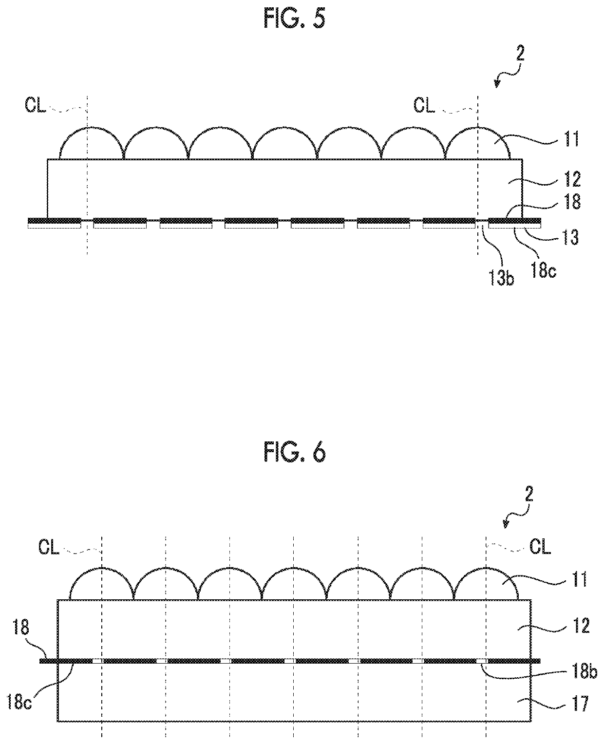
A louver film, a planar light source device, and a liquid crystal display device enables further improvement of directivity for visibility while light use efficiency is maintained and also enable improvement of viewing angle contrast and halo. The louver film includes a plurality of lenses which are arranged at a constant pitch on an emission side of a light source; a first support disposed on a side closer to the light source than the lenses and has a thickness greater than or equal to the pitch of the lenses and a refractive index of 1.5 or greater; and a light reflecting layer disposed on a side closer to the light source than the first support and has a reflectivity of 90% or greater and openings on optical axes of the plurality of lenses, and the opening ratio of each opening is in a range of 30% to 70%.

Description

CROSS-REFERENCE TO RELATED APPLICATIONS[0001]This application is a Continuation of PCT International Application No. PCT / JP2018 / 043575 filed on Nov. 27, 2018, which claims priority under 35 U.S.C. § 119(a) to Japanese Patent Application No. 2017-232869 filed on Dec. 4, 2017 and Japanese Patent Application No. 2018-100798 filed on May 25, 2018. Each of the above applications is hereby expressly incorporated by reference, in its entirety, into the present application.BACKGROUND OF THE INVENTION1. Field of the Invention[0002]The present invention relates to a louver film, and a planar light source device and a liquid crystal display device which comprise a louver film.2. DESCRIPTION OF THE RELATED ART[0003]Since liquid crystal display devices (hereinafter, also referred to as liquid crystal displays (LCDs)) have a low power consumption, the use thereof as space-saving image display devices has increased each year. Each liquid crystal display device is typically configured of a planar l...

Claims


Application Information

Patent Timeline
Patent Type & Authority Applications(United States)
IPC IPC(8): G02F1/1335F21S2/00G02B5/00
CPCG02B5/003G02F2201/343F21S2/00G02F1/133536G02B2207/123G02F1/1323G02F1/133607G02B6/0053G02B27/30G02F1/133606G02F1/133507
Inventor SEKIGUCHI, MEGUMITAMADA, TAKASHIWATANABE, SHINYA
Owner FUJIFILM CORP
Why Eureka
Try Eureka