Method for manufacturing power device cooler

a technology for power devices and coolers, applied in the direction of manufacturing tools, soldering apparatus, semiconductor/solid-state device details, etc., can solve the problems of increasing heat generation, inability to achieve relative roughness, fine bumps on the surface, etc., to achieve favorable joining, reduce costs, and improve productivity

Active Publication Date: 2020-10-08
NIPPON LIGHT METAL CO LTD
View PDF0 Cites 3 Cited by
  • Summary
  • Abstract
  • Description
  • Claims
  • Application Information

AI Technical Summary

Benefits of technology

[0017]According to the present invention, the following effects can be achieved by the configurations described above.
[0018](1) According to the invention described in claim 1, since the condition of the heat receiving surface of the first and second cases that is joined to the heating element is stabilized to ensure the relative roughness thereof, not only is it possible to accomplish cost reduction and favorable joining between the heat receiving surface and the heating element equipped with a power device, but also the productivity can be improved.
[0019](2) According to the invention described in claim 2, since the condition of the surface including the heat receiving surface of the first and second cases that is joined to the heating element is stabilized to ensure the relative roughness thereof, the appearance of the exterior of the cooler can be improved in addition to accomplishing the effect (1) described above.
[0020](3) According to the invention described in claim 3, by Ni-plating the heat receiving surface, not only is it possible to realize favorable joining between the heat receiving surface and the heating element but also a Ni-plated film of uniform thickness can be formed on the heat receiving surface. Therefore, in addition to the effects of (1) above, the heat receiving surface can favorably be joined to the heating element equipped with the power device, and the quality of the cooler can be improved.
[0021](4) According to the invention described in claim 4, by Ni-plating the surface of the first and second cases, the surface can favorably be joined to the heating element and a Ni-plated film of uniform thickness can be formed on the surface of the first and second cases. Therefore, in addition to the effects of (2) above, the surface can favorably be joined to the heating element equipped with the power device, and the appearance of the exterior of the cooler and the quality of the cooler can be improved.

Problems solved by technology

In general, power devices used for inverter control for electric vehicles, hybrid vehicles, air conditioners, and the like and inverter control for various general-purpose motors and the like handle a large amount of electricity, resulting in increasing heat generation.
However, non-corrosive flux brazing that uses a non-corrosive flux and a brazing filler material, which is a typical brazing method, causes attachment of flux residues to the surface, which consequently generates fine bumps on the surface, and for this reason the relative roughness cannot be attained.

Method used


Image

  • Method for manufacturing power device cooler
  • Method for manufacturing power device cooler
  • Method for manufacturing power device cooler

Examples


Embodiment Construction

[0030]Embodiments of a cooler according to the present invention and a method for manufacturing the cooler are now described hereinafter in detail with reference to the accompanying drawings.

[0031]

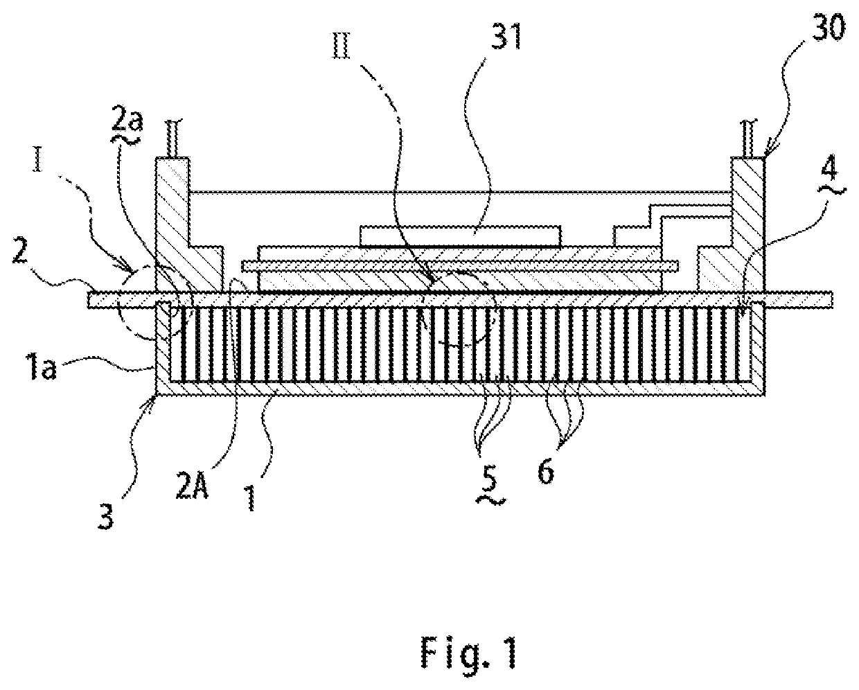
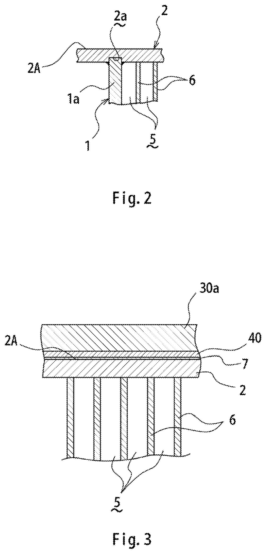
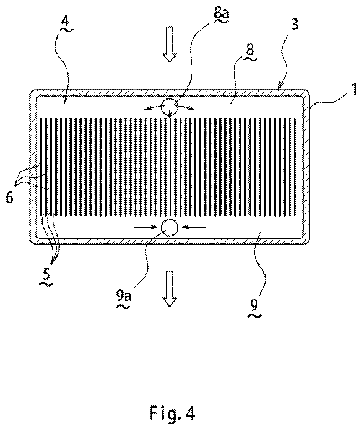
[0032]As shown in FIGS. 1 to 4, a cooler 1 according to the present invention has a first case 1 and a second case 2 made of aluminum alloy that are joined to each other to form a refrigerant circulation space 4 therein, and a plurality of fins 6 made of aluminum (including aluminum alloy) that are arranged in the refrigerant circulation space 4 and each form a refrigerant flow passage 5 along with an adjacent portion, wherein the first and second cases 1, 2 and the fins 6 are joined by a non-corrosive flux and a brazing filler material. In this configuration, of the first and second cases 1 and 2, a surface of the second case 2 is plated with Ni, the surface being a heat receiving surface 2A to be joined to a power module 30 serving as a heating element equipped with a power device 31.

[00...


PUM

PropertyMeasurementUnit
median particle diameteraaaaaaaaaa
relative roughnessaaaaaaaaaa
median particle diameteraaaaaaaaaa

Abstract

To provide a method for manufacturing a power device cooler, which not only can accomplish cost reduction and preferable joining between the cooler and a heating element equipped with a power device but also can improve the productivity. After first and second cases and fins that constitute a cooler are brazed by means of a non-corrosive flux and a brazing filler material, the first and second cases and the fins being made of aluminum, flux residues that are attached at least to a heat receiving surface of the first and second cases that is to be joined to a heating element equipped with a power device, are removed by a wet blasting method in which a mixture of an abrasive formed of polygonal alumina particles having a median particle diameter of 4 to 250 μm and a liquid is projected onto the heat receiving surface by compressed air.

Description

TECHNICAL FIELD[0001]The present invention relates to a method for manufacturing a power device cooler for cooling heat generated from a power device used in a power converter such as an inverter and a converter.BACKGROUND ART[0002]In general, power devices used for inverter control for electric vehicles, hybrid vehicles, air conditioners, and the like and inverter control for various general-purpose motors and the like handle a large amount of electricity, resulting in increasing heat generation. It is therefore necessary to cool the power devices by dissipating the generated heat.[0003]As this type of conventional cooler, there has been known a cooler configured by braze-joining two aluminum plate members and aluminum fins interposed between these plate members (see PTL 1, for example).[0004]Incidentally, in this type of cooler, a heat receiving surface thereof, which is joined to a heating element (power module) equipped with a power device, needs to ensure a relative roughness o...

Claims


Application Information

Patent Timeline
Patent Type & Authority Applications(United States)
IPC IPC(8): H01L21/48B23K1/00
CPCH01L21/4882B23K2103/10B23K1/0008H01L23/473H01L25/07H01L25/18H01L2224/32225H01L23/3735B23K1/0012
Inventor KUBOTA, ETSUROHIRAYAMA, TOMOYUKIHIRANO, YUTAKA
Owner NIPPON LIGHT METAL CO LTD
Why Eureka
Try Eureka