Eureka AIR delivers breakthrough ideas for toughest innovation challenges, trusted by R&D personnel around the world.

Flexible cover window

Active Publication Date: 2020-10-29
UTI INC
View PDF0 Cites 1 Cited by
  • Summary
  • Abstract
  • Description
  • Claims
  • Application Information

AI Technical Summary

Benefits of technology

The present invention proposes a flexible cover window for a flexible display with improved visibility and folding properties. The window is made of glass and has a folding part filled with transparent resin material. The folding part allows for flexibility while maintaining the strength and texture of glass. The transparent resin layer provides uniform coverage of the entire window. Overall, the invention allows for a flexible cover window that enhances visibility and provides a better user experience for flexible displays.

Problems solved by technology

However, since such a polymer film is weak in mechanical strength, the polymer film serves only to prevent scratches of the display panel and is vulnerable to external impacts.
Furthermore, the polymer film has a low transmittance and is known to be relatively expensive.
In addition, in the case of the polymer film, as the number of times the display is folded increases, marks remain on the folding part, which inevitably damages the folding part.
In this case, when folding is repeated, thick parts break during the folding.
As for the folding part having a curved shape, it is not easy to align its center during mechanical assembly, so assembly tolerances may occur, which may result in deterioration of product quality and quality difference between products.
In this case, space (an air layer) is formed between the folding part and the surface of the display panel, which causes the problem of distortion of image quality due to difference in a refractive index between glass and the air layer.
Furthermore, the folding part is damaged due to the pressure of a touch pen or is lowered in durability since a bonding force between portions adjacent to the folding part and the display panel is decreased.
FIG. 2 illustrates a case in which a reflective surface of the boundary part between the folding part and the plane area is visible to the naked eye, which causes distortion of a screen and reduces resolution of a screen.
This problem is required to be improved when the flexible cover window is applied.

Method used


Image

  • Flexible cover window
  • Flexible cover window
  • Flexible cover window

Examples


Embodiment Construction

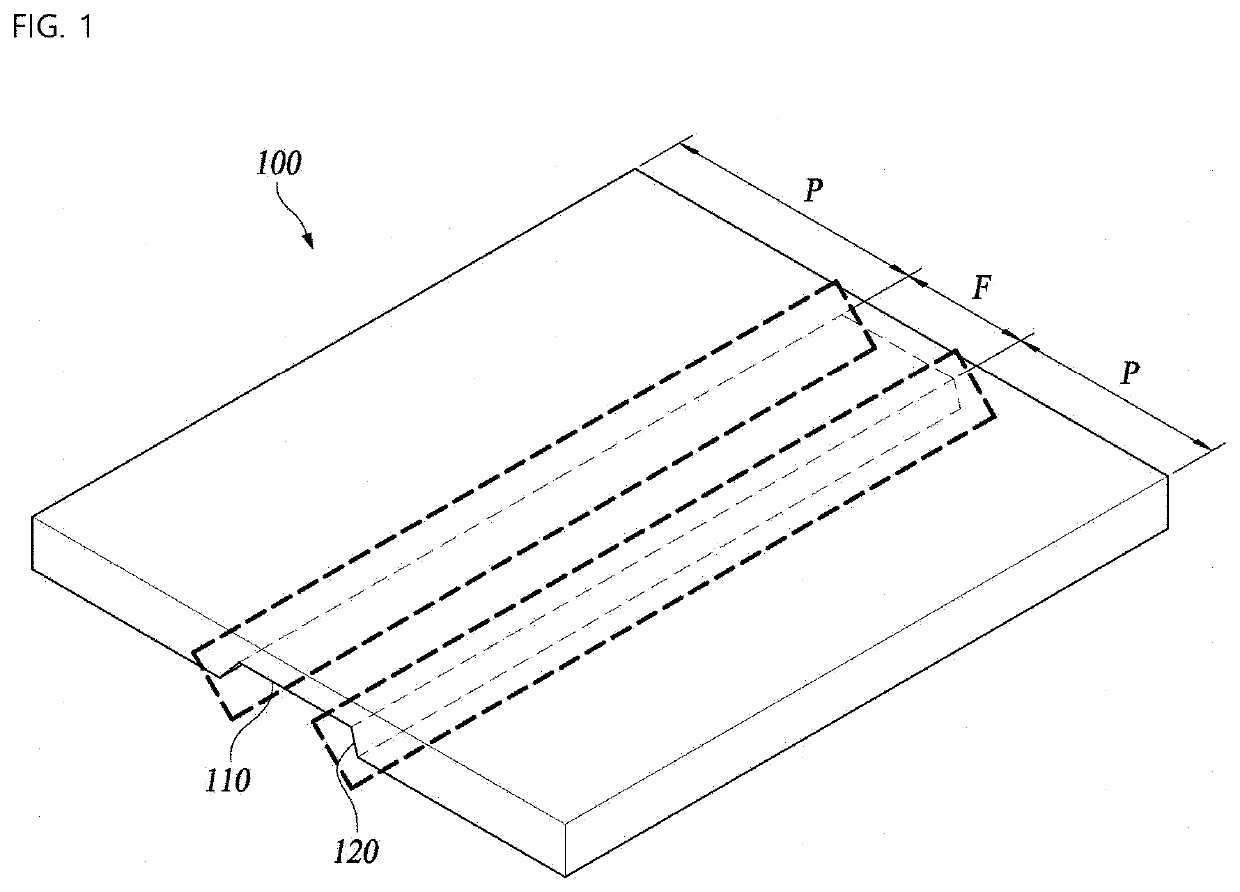
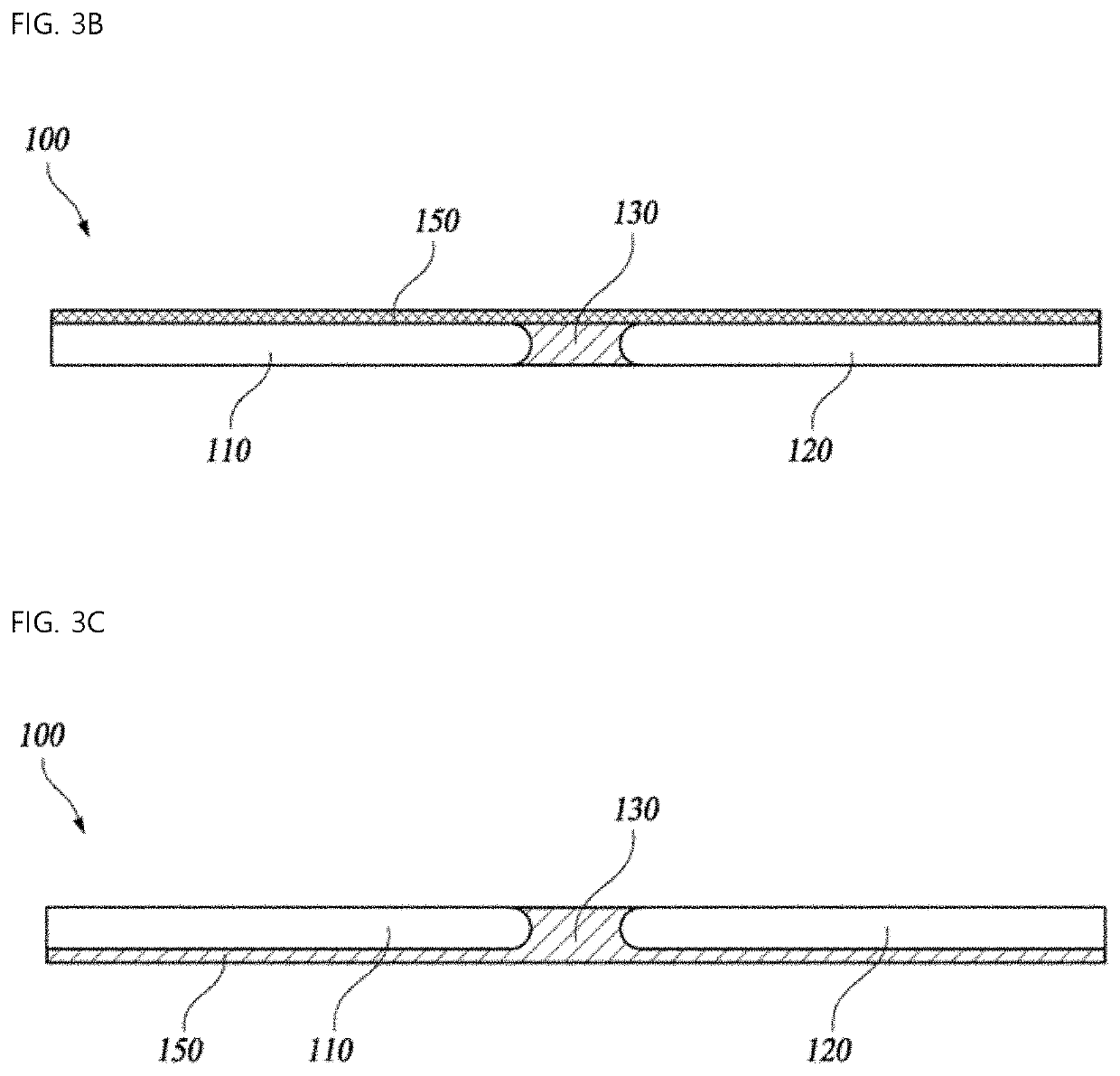
[0043]The present invention generally relates to a flexible cover window. More particularly, the present invention relates to a flexible cover window, in which visibility of a boundary part of a folding part, that is, visibility of a boundary part to the naked eye due to the reflection of a boundary surface of glass is minimized, and strength and folding properties are secured.

[0044]In addition, the flexible cover window according to the present invention is made of a composite material of glass and a transparent resin material, so that flexibility, resilience, elasticity, and strength properties are reinforced due to the resin material while the texture of glass is maximally maintained.

[0045]Furthermore, according to the flexible cover window of the present invention, the limitation of the thickness of the folding part due to the use of the existing glass is minimized due to the use of the composite material of glass and the resin material, so folding and strength properties are im...


PUM


Abstract

A cover window is proposed. Particularly, a flexible cover window having improved visibility for a flexible display is proposed, the flexible cover window including: a first window made of glass and provided on an upper part of a first surface of the flexible display; a second window made of glass and provided on an upper part of a second surface of the flexible display; and a folding part provided between the first window and the second window by corresponding to a folding area of the display and filled with a transparent resin material, wherein a transparent resin layer is provided on a total surface of each of the first window and the second window by continuing to the folding part filled with the transparent resin material.

Description

CROSS REFERENCE TO RELATED APPLICATION[0001]The present application claims priority to Korean Patent Application No. 10-2019-0049109, filed Apr. 26, 2019, the entire contents of which is incorporated herein for all purposes by this reference.BACKGROUND OF THE INVENTIONField of the Invention[0002]The present invention generally relates to a flexible cover window. More particularly, the present invention relates to a flexible cover window, in which visibility of a boundary part of a folding part, that is, visibility of a boundary part to the naked eye due to the reflection of a boundary surface of glass is minimized, and strength and folding properties are secured.Description of the Related Art[0003]Recently, electric and electronic technologies have been rapidly developed, and various types of display products are released to meet demands of a new era and various consumer demands. Among them, research on a flexible display in which the screen can be folded and unfolded is active.[000...

Claims


Application Information

Patent Timeline
IPC IPC(8): G09F9/30
CPCG09F9/301G06F1/1641G06F1/1652G02B1/14
Inventor PARK, DEOK YOUNGHWANG, JAE YOUNGKIM, HAK CHULSUNWOO, KUKHYUNHA, TEA JOO
Owner UTI INC
Why Eureka
Eureka Blog
Learn More