
Active gas generation apparatus

a gas generation apparatus and active technology, applied in the direction of vacuum evaporation coating, plasma technique, coating, etc., can solve the problems of metal contamination in the semiconductor deposition process, the insulation breakdown of the surrounding gas layer, and the inability to avoid the concentration of electric field intensity, so as to reduce product cost and improve efficiency. , the effect of high accuracy

Active Publication Date: 2020-10-29
TOSHIBA MITSUBISHI-ELECTRIC IND SYST CORP
View PDF0 Cites 2 Cited by
  • Summary
  • Abstract
  • Description
  • Claims
  • Application Information

AI Technical Summary

Benefits of technology

The present invention relates to an apparatus for generating active gas, which can reliably prevent the mixing of evaporation materials and produce high-quality active gas. This is achieved through the separation of gas flow in the discharge space and the alternating-current voltage application space using auxiliary members. Additionally, misalignment of the electrodes is reduced, which reduces the possibility of anomalous discharge and increases the strength of the components. The apparatus also ensures stable and accurate gap length without the necessity of additional parts, which lowers the overall cost of production.

Problems solved by technology

However, from a microscopic viewpoint, it is impossible to avoid concentration of electric field intensity enough to cause insulation breakdown of a surrounding gas layer due to the shape and surface state of a metal component of the power supply part.
When the nearby component is made of metal, the above-described phenomenon causes metal contamination in a semiconductor deposition process.

Method used


Image

  • Active gas generation apparatus
  • Active gas generation apparatus
  • Active gas generation apparatus

Examples


embodiment

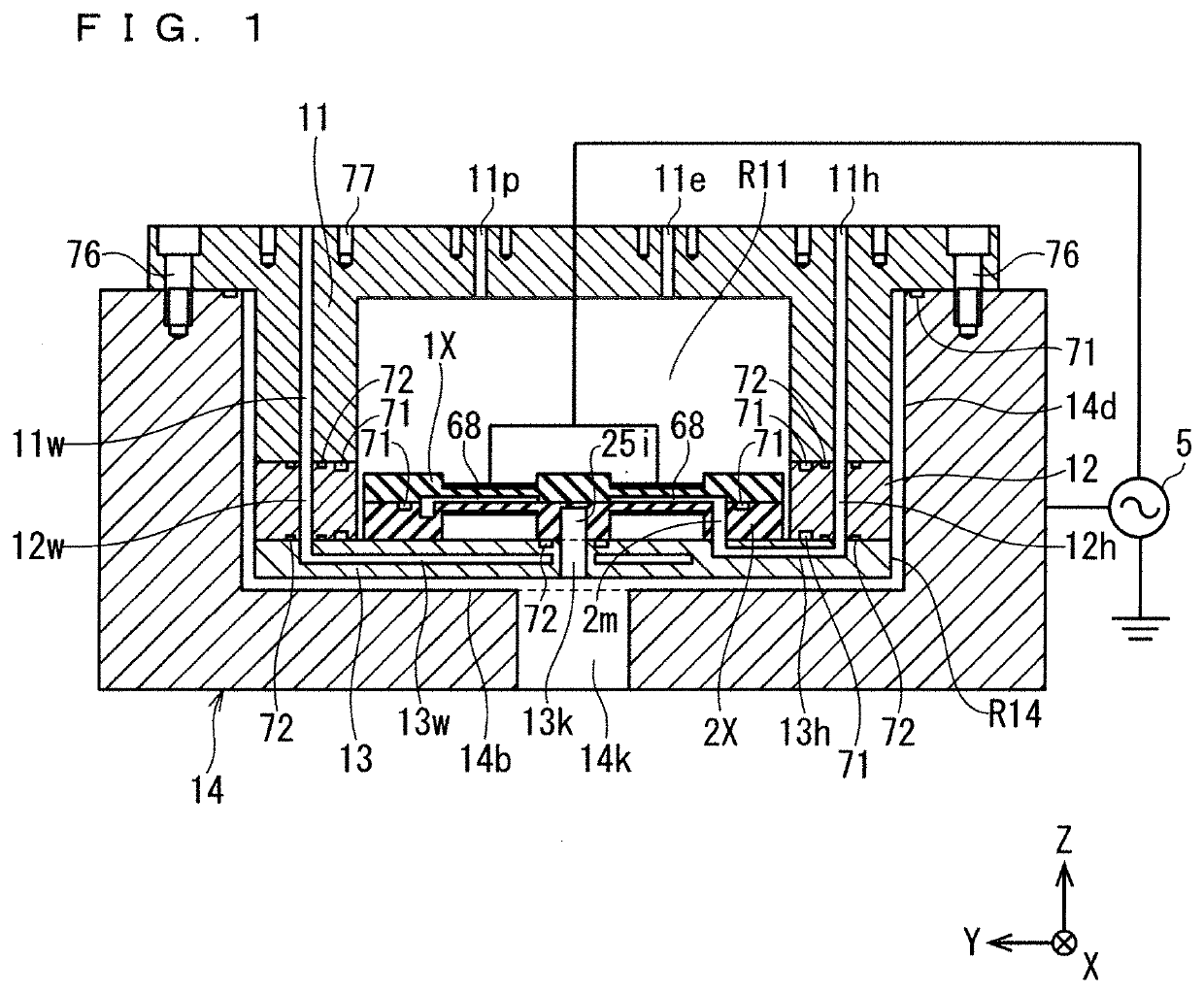
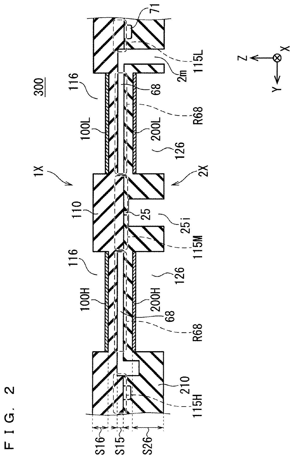
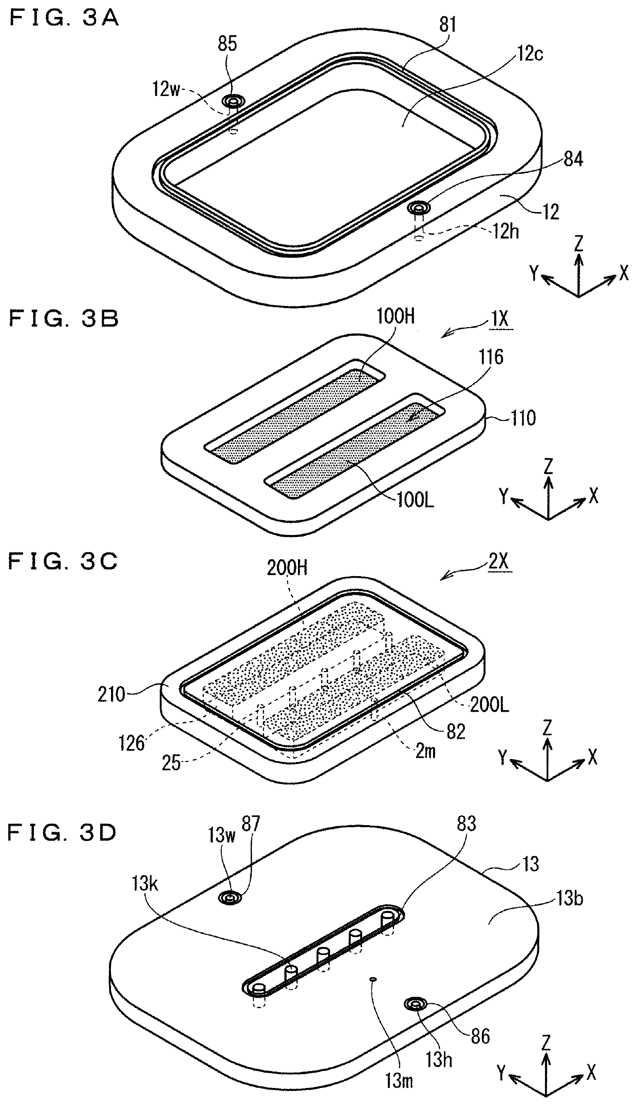
[0110]FIG. 1 is an explanatory diagram schematically illustrating a cross-sectional structure of an active gas generation apparatus according to an embodiment of the present invention. FIG. 2 is an explanatory diagram illustrating a cross-sectional configuration of an active gas generation electrode group 300. FIG. 3 is an explanatory diagram illustrating a main configuration part of the active gas generation apparatus according to the embodiment in a disassembled state. Note that FIGS. 1 to 3 each show an XYZ orthogonal coordinate system.

[0111]As illustrated in FIG. 2, FIG. 3(b) and FIG. 3(c), the active gas generation electrode group 300 includes a high-voltage side electrode component 1X (first electrode component) and a ground side electrode component 2X (second electrode component) provided below the high-voltage side electrode component 1X.

[0112]A dielectric electrode 110 (first dielectric electrode) of the high-voltage side electrode component 1X and a dielectric electrode 21...


PUM

PropertyMeasurementUnit
frequencyaaaaaaaaaa
pressureaaaaaaaaaa
atmospheric pressureaaaaaaaaaa

Abstract

The present invention has features (1) to (3). The feature (1) is that “an active gas generation electrode group is formed in such a manner that a ground side electrode component supports a high-voltage side electrode component”. The feature (2) is that “stepped parts are provided in a discharge space outside region of a dielectric electrode in the high-voltage side electrode component, and project downward, and by a formation height of these stepped parts, the gap length of a discharge space is defined”. The feature (3) is that “the high-voltage side electrode component and the ground side electrode component are formed to have the thickness of a discharge space formation region relatively thin and the thickness of a discharge space outside region relatively thick”.

Description

TECHNICAL FIELD[0001]The present invention relates to an active gas generation apparatus including two electrodes installed in parallel to obtain active gas through energy of discharge caused by applying high voltage between the electrodes.BACKGROUND ART[0002]In an active gas generation apparatus including two electrodes installed in parallel to obtain active gas through the energy of a discharge phenomenon caused in a discharge space between the electrodes by applying high voltage between the electrodes, typically, alternating-current high voltage is applied to one of the electrodes, and the other electrode is set to a reference voltage such as a ground level.[0003]In such an active gas generation apparatus, a high voltage of several kVrms (root mean square) is applied to one of electrodes as a high voltage power supply part. In a space other than the discharge space formed between the pair of electrodes, the distance between the power supply part and a ground part (the other elect...

Claims


Application Information

Patent Timeline
Patent Type & Authority Applications(United States)
IPC IPC(8): H01J37/32C23C16/452C23C16/50C23C16/455
CPCC23C16/452H01J37/3244H01J37/32568H01J37/32082H01J37/32348C23C16/50H01J2237/002H01J2237/332C23C16/455H05H1/2406C23C14/0026B01J12/002B01J2219/0815B01J2219/0809B01J19/088H05H1/30H05H1/2418
Inventor WATANABE, KENSUKENISHIMURA, SHINICHIARITA, RENYAMADA, YOSHIHITOTABATA, YOICHIRO
Owner TOSHIBA MITSUBISHI-ELECTRIC IND SYST CORP
Learn More