
Air-Cooled Heat Exchanger and Thermal Arrangement for Stacked Electronics

a heat exchanger and stacking technology, applied in the field of packaging and improving the cooling of electronic components, to achieve the effect of high power density electronics and similar level of performan

Active Publication Date: 2020-11-05
TELEPHONICS
View PDF0 Cites 0 Cited by
  • Summary
  • Abstract
  • Description
  • Claims
  • Application Information

AI Technical Summary

Benefits of technology

The patent aims to provide a more efficient cooling system for high power density electronics using air-cooled heat exchangers to replace the need for a complex liquid-cooled system. The technical effect of this invention is to achieve a similar level of performance while eliminating the need for a liquid-cooled system.

Problems solved by technology

The packaging of modern electronics often must address multiple issues apart from the packaging envelope, including cooling adequacy, the potential for mechanical damage, radio frequency noise emission, protection from electrostatic discharge, accessibility and maintenance, cost, etc.

Method used


Image

  • Air-Cooled Heat Exchanger and Thermal Arrangement for Stacked Electronics
  • Air-Cooled Heat Exchanger and Thermal Arrangement for Stacked Electronics
  • Air-Cooled Heat Exchanger and Thermal Arrangement for Stacked Electronics

Examples


first embodiment

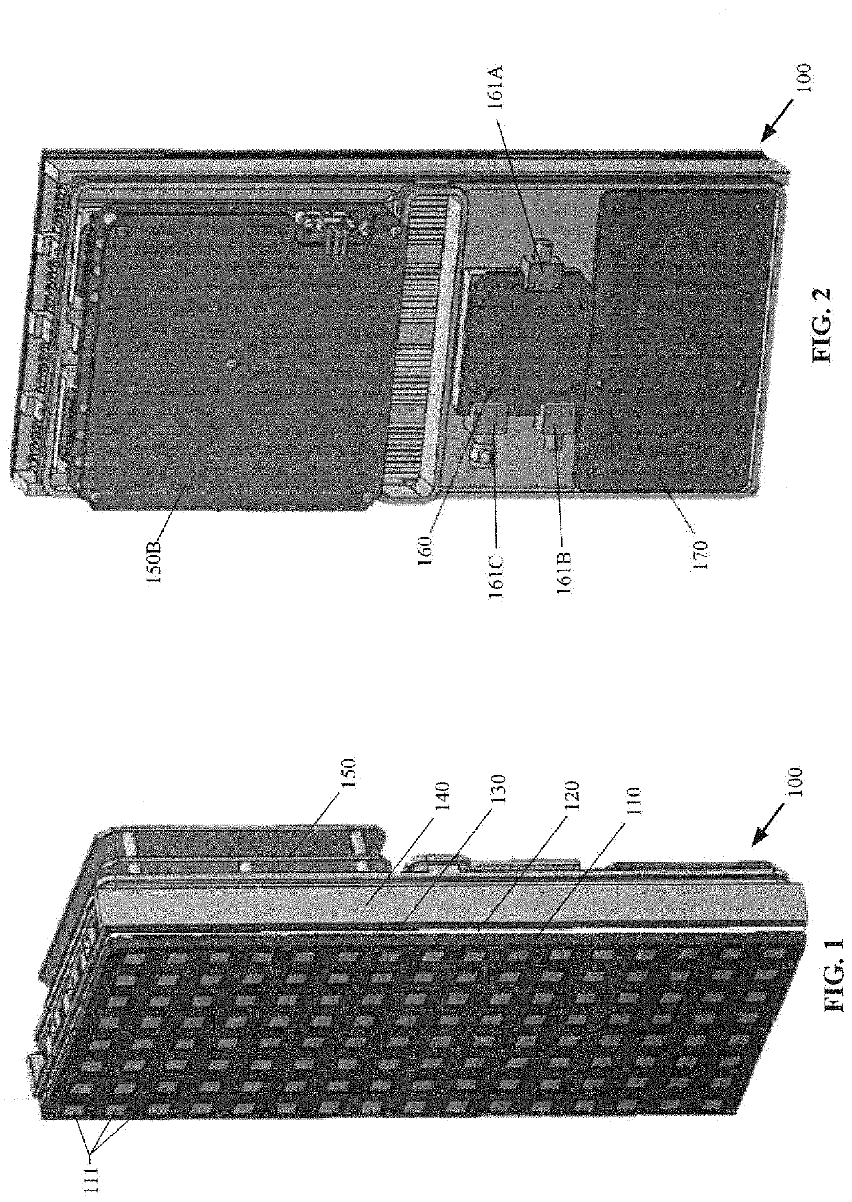
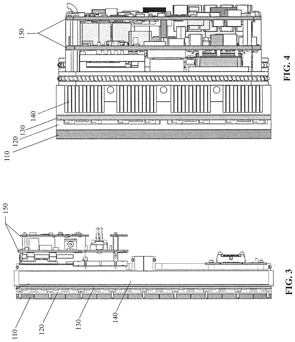
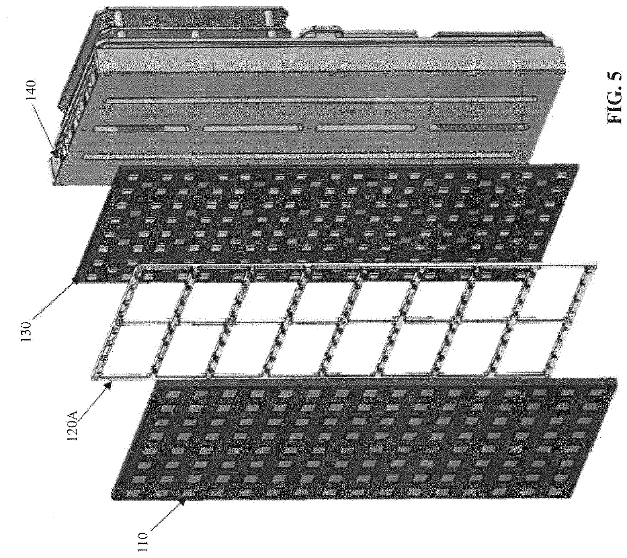
[0124]FIGS. 1-4 illustrate perspective, side, and top views of a stacked electronics package 100, and FIGS. 6A-8 illustrate exploded views of the component parts of that stacked electronics package. As seen therein, the stacked electronics package 100 may include a passive radiator circuit card assembly 110, a tile frame 120, an active tile circuit card assembly 130, a heat exchanger 140, a tile power converter 150, a tile combiner 160, and a tile controller circuit card assembly 170. Each circuit card assembly (CCA) herein may include a printed circuit board populated with electronic components that may include millimeter monolithic integrated circuits (MIMICs).

[0125]The passive radiator circuit card assembly 110 may be formed, in one embodiment, of a plurality of radiating elements 111 (e.g., patch radiators plugins) that may be imprinted into the inner board layers. Each radiator plug-in may be formed of a printed wiring board (PWB) stack-up of various RF materials (e.g., RO3003™...

second embodiment

[0141]FIG. 37 is a colored thermal plot of a heat exchanger formed to be different than the heat exchanger of FIGS. 16-18 and FIGS. 20A, 21A, 22A, and 22B, as it has air intake at only one end, and air exhaust at the opposite end;

[0142]The heat exchanger 140 with a double inlet having an inlet at each of the opposite ends and the common central exhaust plenum serves to create a very uniform temperature gradient across all components within the electronic system.

[0143]Both FIG. 37 and FIG. 40 represent steady state conditions, but there is a difference in the maximum temperature reached; the single intake heat exchanger in FIG. 37 reaches a maximum temperature of 92.77° C., while the dual intake heat exchanger of FIG. 40 reaches a maximum temperature of 84.33° C., which temperature may result from a mass flow rate of about 3.2 lbs / min.

[0144]FIGS. 33-36 illustrate a multi-member array of stacked electronics packages, each formed in accordance with the embodiment of FIG. 1;

[0145]FIGS. ...


PUM


Abstract

A stacked electronic arrangement provides independent upgradability of active component boards and radiator boards, enabling quick changes in chip set and alternate polarizations, and includes: an active tile circuit card assembly (CCA); a passive radiator CCA; a tile frame; and a heat exchanger. The active tile CCA includes transmit / receive modules that accept, amply and transmit radar signals. The passive radiator CCA includes patch radiator plugins that receive and then radiate the amplified signal from the modules. The tile frame separates the active tile and the passive radiator CCAs. An elongated casing of the heat exchanger creates an accommodating space for air flow, and forms a first inlet, a second inlet, and a central exhaust plenum between the first and second inlets. High density fins are positioned within the accommodating space between the first and second inlets, and which have openings to the exhaust outlet.

Description

CROSS REFERENCES TO RELATED APPLICATIONS[0001]This application is a divisional of U.S. application Ser. No. 16 / 203,999, filed on Nov. 20, 2018, which is a continuation in part of U.S. application Ser. No. 16 / 188,998, filed on Nov. 13, 2018, which claims priority on U.S. Provisional Application Ser. No. 62 / 585,019 filed on Nov. 13, 2017, all disclosures of which are incorporated herein by reference.FIELD OF THE INVENTION[0002]The disclosed apparatus relates to packaging and improved cooling of electronic components that includes a plurality of Monolithic Microwave Integrated Circuits (MMICs) for a radar antenna, and more particularly to a more efficient cooling arrangement in terms of size, weight, power and cost, that eliminates the need for a complex liquid cooled system to enable high ambient temperatures.BACKGROUND OF THE INVENTION[0003]Electronics packaging has become a major discipline within the field of electronic engineering. Some educational institutions, including the Univ...

Claims


Application Information

Patent Timeline
Patent Type & Authority Applications(United States)
IPC IPC(8): H05K1/14H05K1/02H05K7/02
CPCH05K1/0203H05K7/02H05K1/0272H05K1/144H01Q1/02H01Q21/0025H01Q21/0087
Inventor MCPARTLAND, GEORGEVAYSMAN, ALEKSANDER
Owner TELEPHONICS
Learn More