Eureka AIR delivers breakthrough ideas for toughest innovation challenges, trusted by R&D personnel around the world.

Turbomachine fan flow-straightener vane, turbomachine assembly comprising such a vane, and turbomachine equipped with said vane or with said assembly

a technology of turbomachine and fan, which is applied in the direction of machines/engines, stators, liquid fuel engines, etc., can solve the problems of reducing the formation, generating noise, and significantly affecting the vortex, so as to limit the drag of the turbomachine nacelle and the mass of the propulsion assembly

Active Publication Date: 2020-11-12
SN DETUDE & DE CONSTR DE MOTEURS DAVIATION S N E C M A
View PDF0 Cites 5 Cited by
  • Summary
  • Abstract
  • Description
  • Claims
  • Application Information

AI Technical Summary

Benefits of technology

This patent is about improving the design of a fan casing for a bypass turbomachine. The invention involves adding a row of flow-straightener vanes downstream of the fan vanes to reduce drag and noise in the fan casing. The shape of the flow-straightener vane is designed to minimize the interaction with the fan vanes and to maintain a minimum axial distance between the vanes. This design helps to achieve a quieter and more streamlined fan casing, which can ultimately reduce the acoustic criterion in the upper part of the nacelle. In summary, the technical effects of this patent are improved aerodynamic performance and reduced acoustic impact.

Problems solved by technology

Such a configuration reduces the formation of vortices, which also generate noise.
Indeed, a sudden change would significantly affect the vortices that can form in the upper part of the vane and which are a source of noise.

Method used


Image

  • Turbomachine fan flow-straightener vane, turbomachine assembly comprising such a vane, and turbomachine equipped with said vane or with said assembly
  • Turbomachine fan flow-straightener vane, turbomachine assembly comprising such a vane, and turbomachine equipped with said vane or with said assembly
  • Turbomachine fan flow-straightener vane, turbomachine assembly comprising such a vane, and turbomachine equipped with said vane or with said assembly

Examples


Embodiment Construction

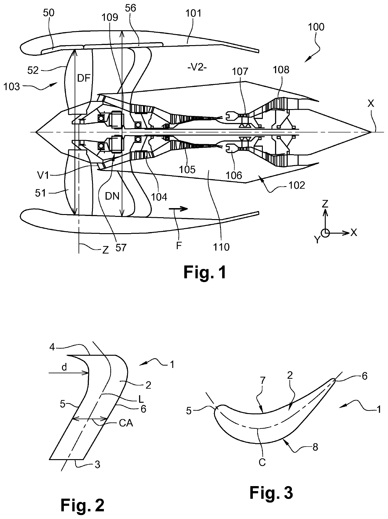
[0028]FIG. 1 illustrates an aircraft turbomachine 100 to which the invention applies. This turbomachine 100 is here a bypass turbomachine extending along a longitudinal axis X. The bypass turbomachine generally comprises an external nacelle 101 surrounding a gas generator 102 upstream of which is mounted a fan 103. In the present invention, and in a general manner, the terms “upstream” and “downstream” are defined in relation to the flow of gases in the turbomachine 100. The terms “upper” and “lower” are defined with respect to a radial axis Z perpendicular to the axis X and with respect to the distance from the longitudinal axis X. A transverse axis Y is also perpendicular to the longitudinal axis X and the radial axis Z. These axes, X, Y, Z form an orthonormal mark.

[0029]In this example, the gas generator 102 comprises, from upstream to downstream, a low-pressure compressor 104, a high-pressure compressor 105, a combustion chamber 106, a high-pressure turbine 107 and a low-pressur...


PUM


Abstract

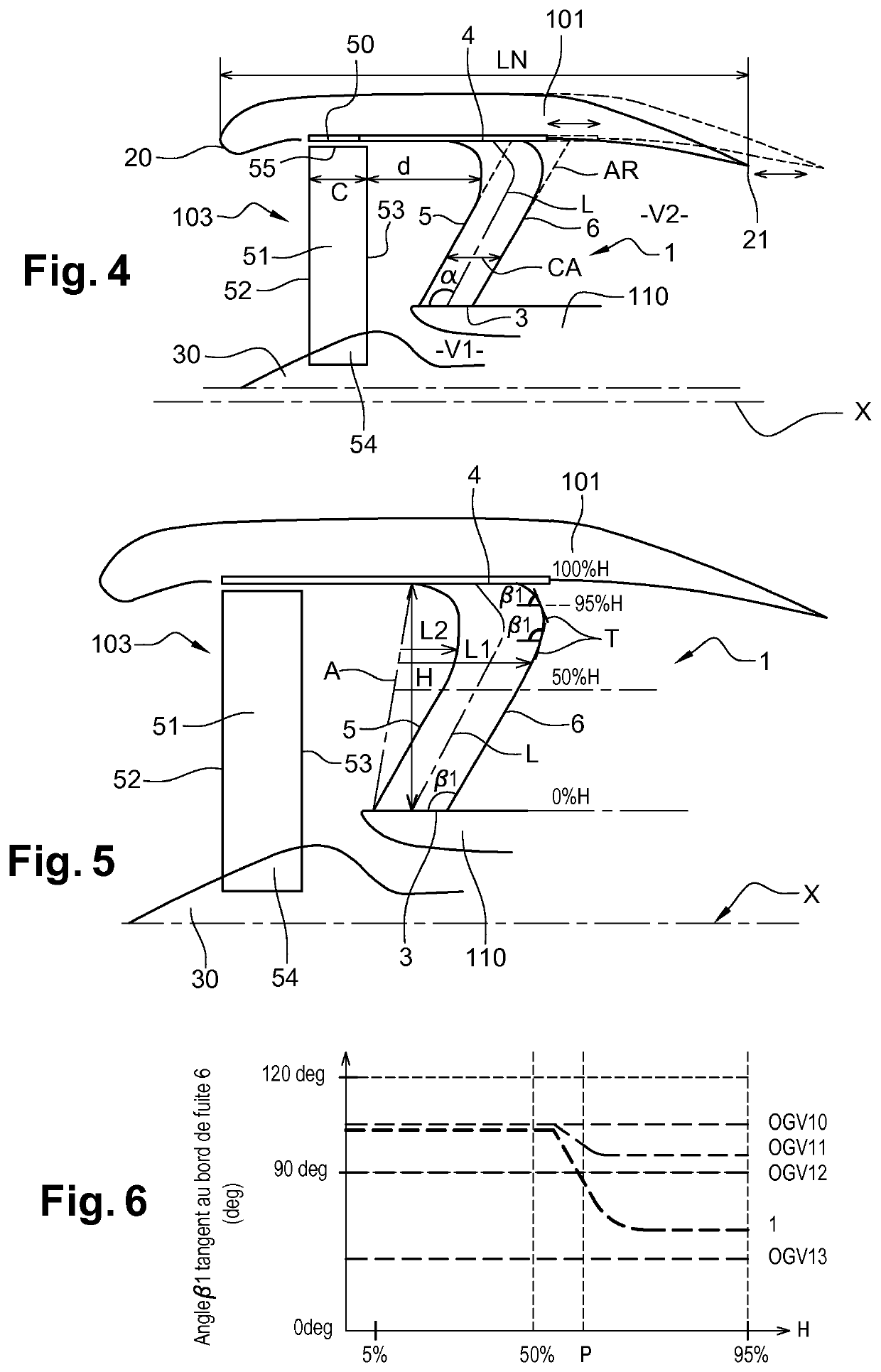
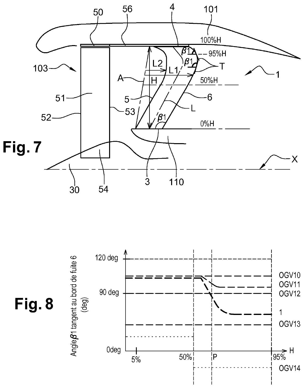
A flow-straightener vane of a bypass turbomachine includes a plurality of vane sections stacked radially with respect to a longitudinal axis (X) along a stacking line (L) between a root end and a tip end. Each vane section has a pressure-face surface and a suction-face surface extending axially between an upstream leading edge and a downstream trailing edge. Between the leading and trailing edges of each vane section there is formed a profile chord (CA) the length of which is substantially constant between the tip end and the root end, and the stacking line (L) exhibits a curvature in a plane passing more or less through the axis (X) and through the stacking line (L), situated in the vicinity of the tip end and oriented from downstream towards upstream.

Description

1. FIELD OF THE INVENTION[0001]The present invention relates to the field of turbomachines. It relates to a turbomachine vane and in particular a fan flow-straightener vane. The invention also concerns an assembly comprising a nacelle and a fan casing which is fixed to the nacelle and which is equipped with at least one flow-straightener vane and a turbomachine equipped with such a vane or such an assembly with a flow-straightener vane.2. BACKGROUND[0002]The natural evolution of multi-flow turbojet engines with a fan, particularly upstream, is to increase the propulsive efficiency by reducing the specific thrust, obtained by reducing the fan compression ratio, which results in an increase in the bypass ratio (BPR), which is the ratio of the mass flow of air through a vein or veins surrounding the gas generator to the mass flow of air through the gas generator, calculated at the maximum thrust when the engine is stationary in an international standard atmosphere at sea level.[0003]Th...

Claims


Application Information

Patent Timeline
Patent Type & Authority Applications(United States)
IPC IPC(8): F01D9/04
CPCF05D2240/125F05D2220/323F01D9/041F01D5/141F04D29/544F04D29/663F05D2250/38
Inventor LEMARCHAND, KEVIN MORGANEJODET, NORMAN BRUNO ANDRÉMARTIN, GUILLAUMESOULAT, LAURENT
Owner SN DETUDE & DE CONSTR DE MOTEURS DAVIATION S N E C M A
Why Eureka
Eureka Blog
Learn More