Three-dimensional molding apparatus and three-dimensional molding method using different types of materials

a three-dimensional molding and molding method technology, applied in the direction of additive manufacturing processes, manufacturing tools, applying layer means, etc., can solve the problems of difficult use of low melting point materials, soft materials, etc., and achieve the effect of improving thermal stability and mechanical properties

Active Publication Date: 2020-12-10
KJ CHEM
View PDF0 Cites 3 Cited by
  • Summary
  • Abstract
  • Description
  • Claims
  • Application Information

AI Technical Summary

Benefits of technology

[0036]By having at least one nozzle having a mechanism for outputting material A and at least one nozzle having a mechanism for outputting material B, the three-dimensional molding apparatus of the present invention is capable of producing a molded product composed of multiple types of materials by using multiple types of molding materials. Material A and material B are selected from a wide variety of molding materials from soft rubber materials to high-strength plastic materials in accordance with the purpose and are output and molded by a single thre

Problems solved by technology

However, molding by combining different types of materials having different mechanical properties was difficult with conventional 3D printers.
The use of low-melting-point materials, soft materials, and the like was therefore difficult when molding by means of fused deposition modeling.
Reduction of the viscosity of the ink (normally less than 20 mPa·s) has therefore been an important issue and the use of a high-viscosity photo-curable resin was difficult.
In addition, since a low-viscosity photo-curable resin has a low molecular weight and it is therefore difficult to achieve practical values for mechanical strength, impact resistance, and the like in the obtained molded product, it is impossible to reproduce all the properties of engineering plastics such as ABS.
The photopolymer therefore flows around the thermoplastic resin, and there was a risk that the photopolymer might penetrate too deeply into thermoplastic members, making curing difficult.
Patent Literature 1 proposes preventing the photopolymer from penetrating too far by forming a solid layer with the thermoplastic material, but since moldable structures and applicable resins and materials are limited, this method could not be considered to be a suitable method for precision three-dimensional molding.
In particular, there were problems that high-viscosity photo-curable materials could not be used and that mechanical properties of the molded product could not be ensured.
However, in this method, too, it was difficult to use a high-viscosity photo-curable resin as a mold material and it was impossible to produce a molded product in combination with a non-phot

Method used


Image

  • Three-dimensional molding apparatus and three-dimensional molding method using different types of materials
  • Three-dimensional molding apparatus and three-dimensional molding method using different types of materials
  • Three-dimensional molding apparatus and three-dimensional molding method using different types of materials

Examples


embodiment 1

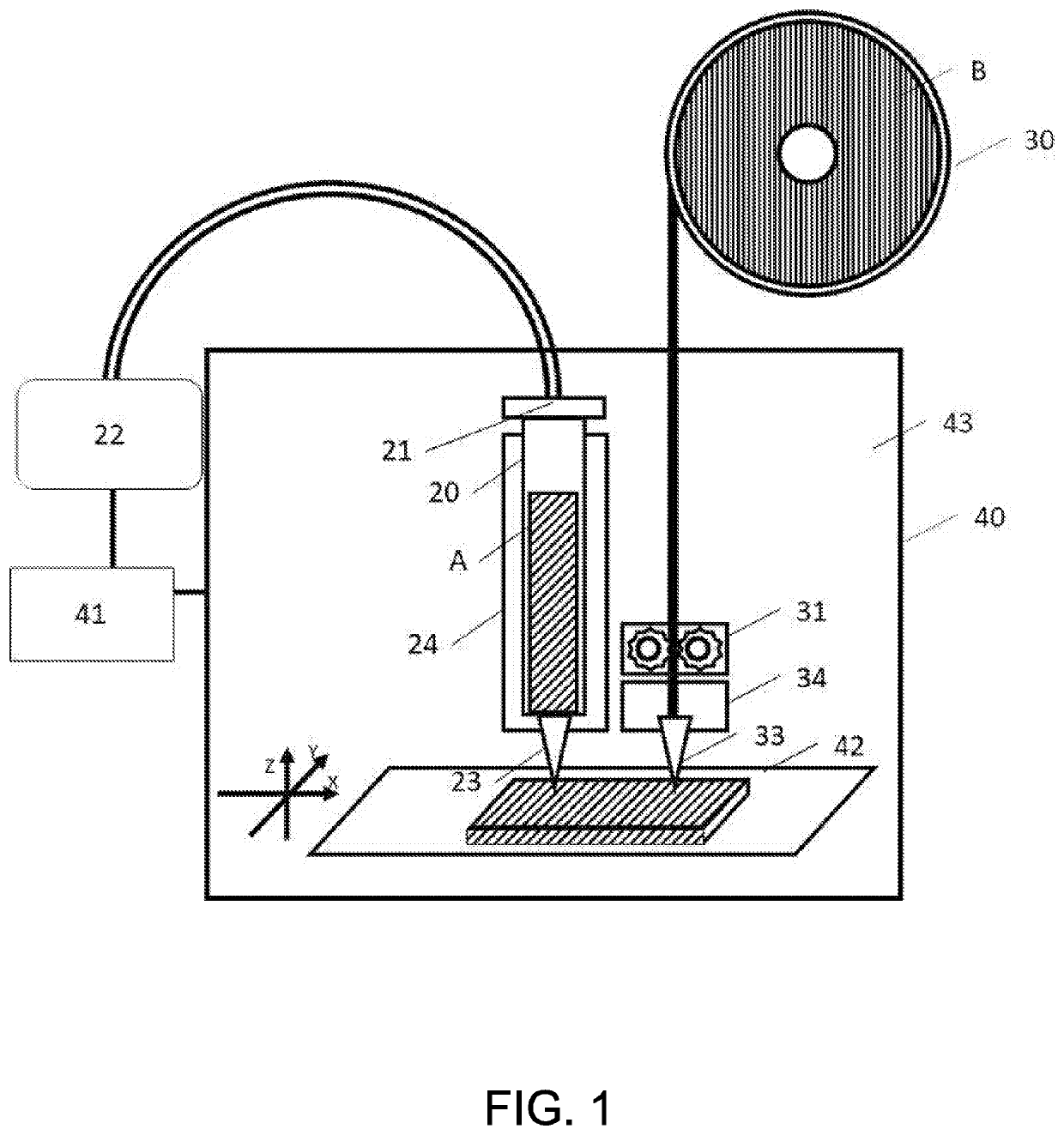
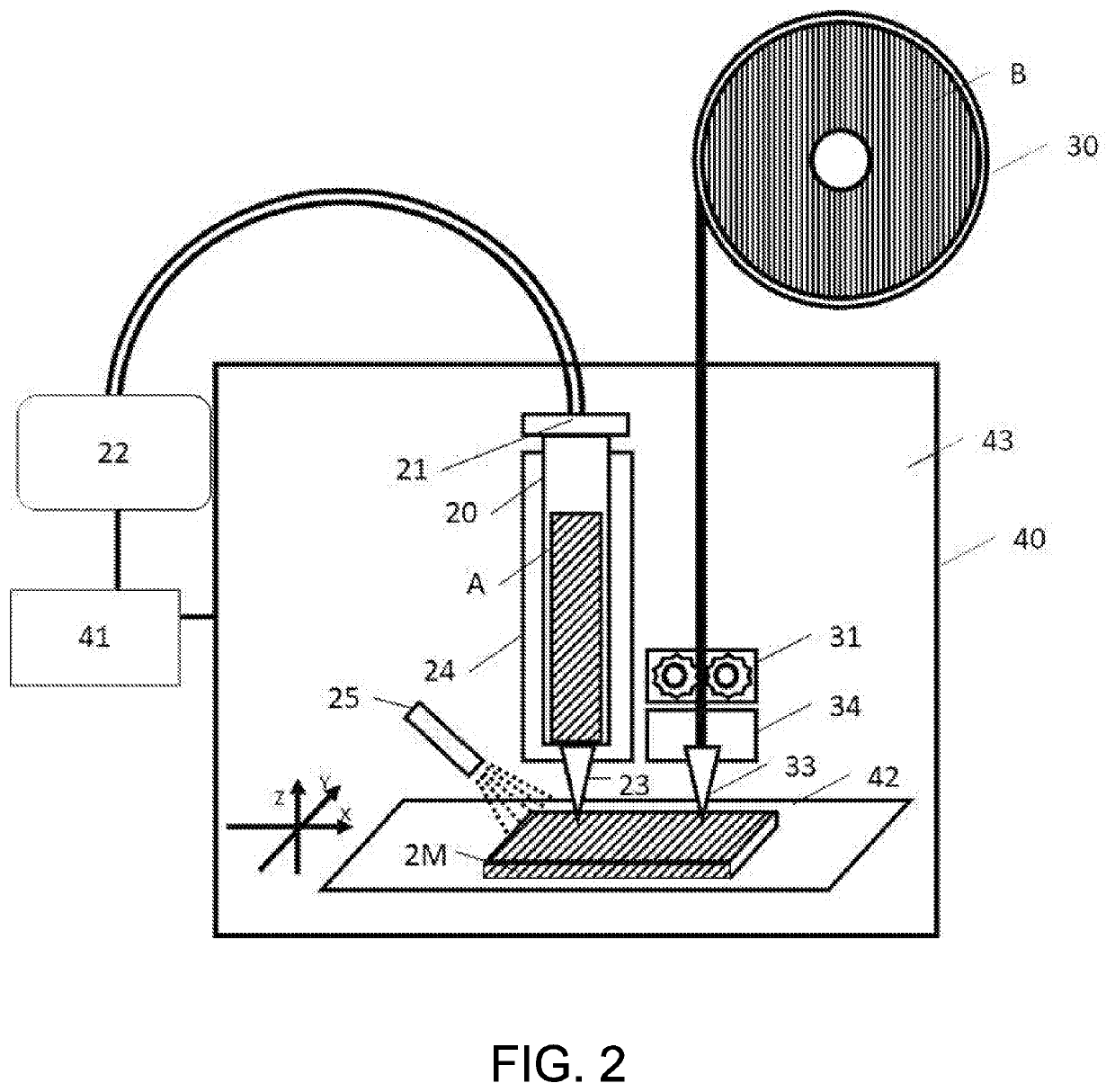
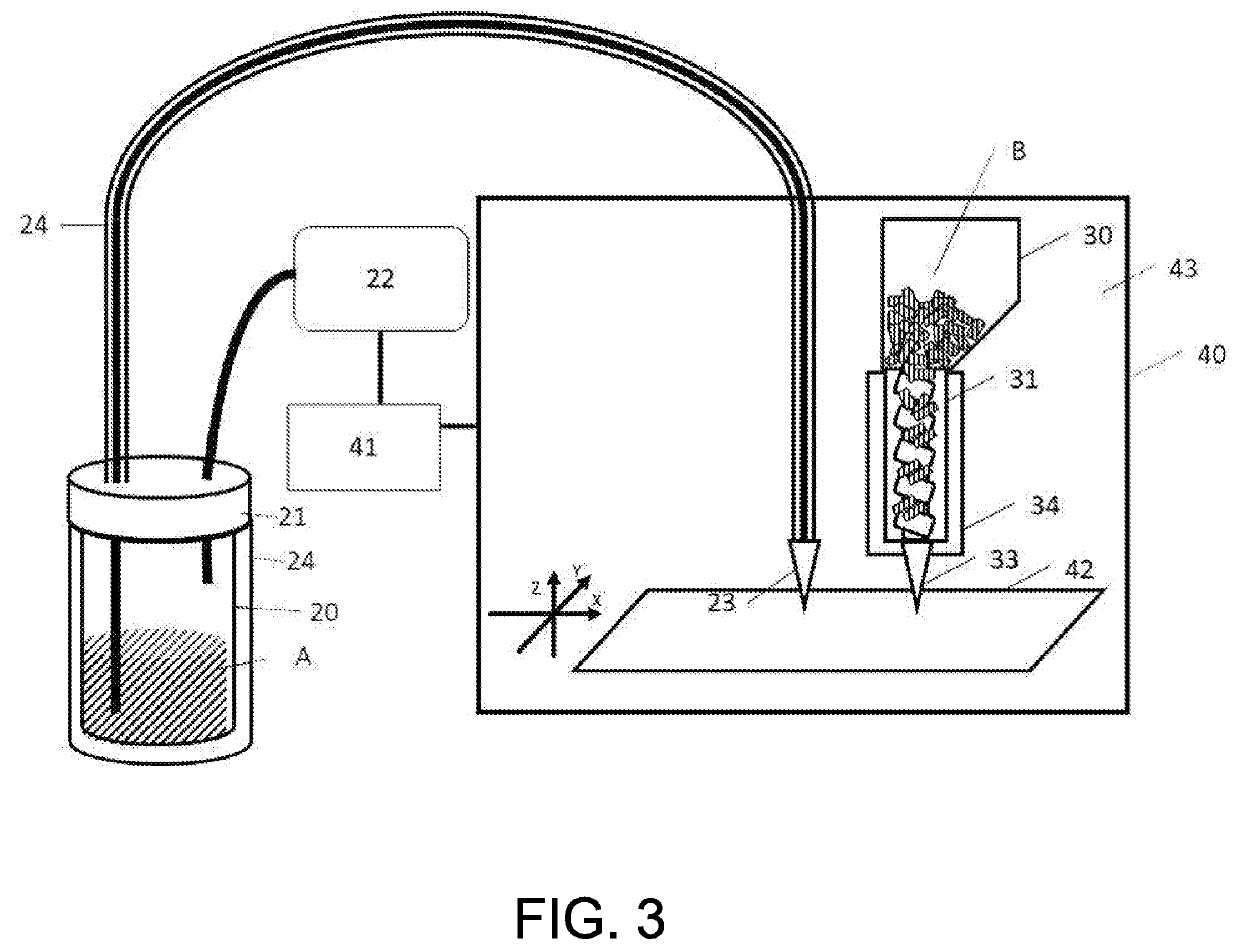
[0126]In an embodiment of the present invention, different types of materials A and B are used and stacked to produce a three-dimensional molded product. As shown in FIG. 1, a three-dimensional molding apparatus which uses a syringe pump as the output mechanism of material A and which comprises a reservoir portion 20 for storing A, a pressurizing portion 21 for applying pressure to A, a pressurization controller portion 22, a nozzle portion 23 for dispensing A, and a heating portion 24 for heating the reservoir portion 20 and the nozzle portion 23;[0127]a reservoir portion 30 for material B, a nozzle portion 33 for dispensing B, and a heating portion 34 and a pressurizing portion 31 related to B;[0128]a stage 42 onto which the molding materials dispensed from the dispensing outlets of the multiple nozzle portions are stacked, and a relative movement mechanism(s) for three-dimensionally relatively moving the stage 42 with respect to the nozzle portion 23 and the nozzle portion 33;[01...

example 1

[0131]A coating chocolate (manufactured by Kyoritsu Foods, viscosity: 42 Pa·s (33° C.)) was used as material A, and the reservoir portion 20 and the nozzle portion 23 (dispensing outlet inner diameter: 2.0 mm, outer diameter: 4.0 mm) were heated to 40° C. PolyPlus PLA (manufactured by Polymaker, MFR: 7 to 11 g / 10 min (210° C., load: 2.16 kg)) was used as material B, and the heating portion 34 and the nozzle portion 33 (dispensing outlet inner diameter: 0.5 mm, outer diameter: 2.0 mm) were heated to 210° C. The environmental temperature of the molding area 43 was set at 10° C., the stacking thickness of A and B was set to 0.6 mm and 0.2 mm, respectively, and molding was carried out in accordance with the prescribed molding speed, pressure, molding pattern, and the like for each material. Each of A and B dispensed onto the stage 42 was cooled and solidified after being dispensed. This operation was performed for each layer, and the layers were further stacked to thereby produce a cyli...

embodiment 2

[0132]As shown in FIG. 4, an apparatus which uses a gear pump as the output mechanism for A and which comprises a reservoir portion 20 for storing A, a pressurizing portion 21 for applying pressure to A, a pressurization controller portion 22, a nozzle portion 23 for dispensing A, and a heating portion 24 for heating the reservoir portion 20 and the nozzle portion 23 was used. A dispensing unit for materials in the form of pellets was used as the output mechanism for B as shown in FIG. 4.


PUM

PropertyMeasurementUnit
Temperatureaaaaaaaaaa

Abstract

A three-dimensional molding apparatus is provided and includes a reservoir portion, a nozzle portion, a liquid-sending unit, and a temperature control unit that correspond to each of the two or more different types of materials, a molding stage, a relative movement mechanism for moving the stage and the nozzle portions, and a control computer. By using this apparatus, industrial additive manufacturing with two or more different types of materials can be realized with high precision, and high-definition molded products in which different types of materials are arbitrarily combined can be produced.

Description

TECHNICAL FIELD[0001]The present invention relates to a three-dimensional molding apparatus, a three-dimensional molding method, and a three-dimensional molded product using different types of materials.BACKGROUND ART[0002]3D printers are generally applied as a technique for producing three-dimensional molded products by using 3D-CAD data. Three-dimensional molding apparatuses for three-dimensionally molding various materials such as metals, plastics, and foods are beginning to be used in various fields.[0003]Many actual industrial products are produced by combining different types of materials having different mechanical properties rather than by using a single material. However, molding by combining different types of materials having different mechanical properties was difficult with conventional 3D printers.[0004]For example, in fused deposition modeling, although multiple molding materials can be dispensed at the same time, since every material must be dispensed from a nozzle h...

Claims


Application Information

Patent Timeline
IPC IPC(8): B29C64/124B29C64/393B29C64/336B29C64/209B29C64/255B29C64/232B29C64/236B29C64/264
CPCB29C64/393B29C64/236B29C64/124B29C64/232B29C64/264B29C64/255B29C64/209B29C64/336B33Y30/00B33Y10/00B29C64/106B29C64/194B33Y40/00B33Y50/02B33Y70/10B29C48/02B29C48/92B29C48/16B29C48/05B22F12/55B22F10/10B22F10/12Y02P10/25B29C64/227B29C64/245B29C64/321B33Y70/00
Inventor KUNIHIRO, YOSHIOISHIMARU, YUYA
Owner KJ CHEM
Why Eureka
Try Eureka