

Devices And Methods To Infuse Gases Into And Out Of Blood
a technology of gas infusion device and blood, which is applied in the direction of catheter, other blood circulation device, transportation and packaging, etc., can solve the problems of gas leakage into surrounding fluid, bubble rupture or leakage, etc., and achieve the effect of reducing the diameter of any bubbl
- Summary
- Abstract
- Description
- Claims
- Application Information
AI Technical Summary
Benefits of technology
Problems solved by technology
Method used
Image

Examples
embodiment 10
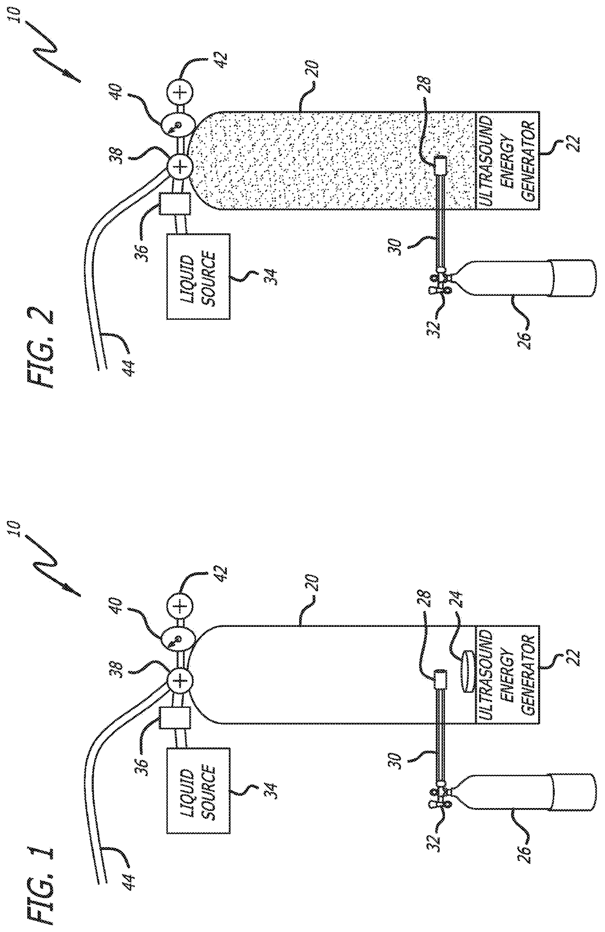
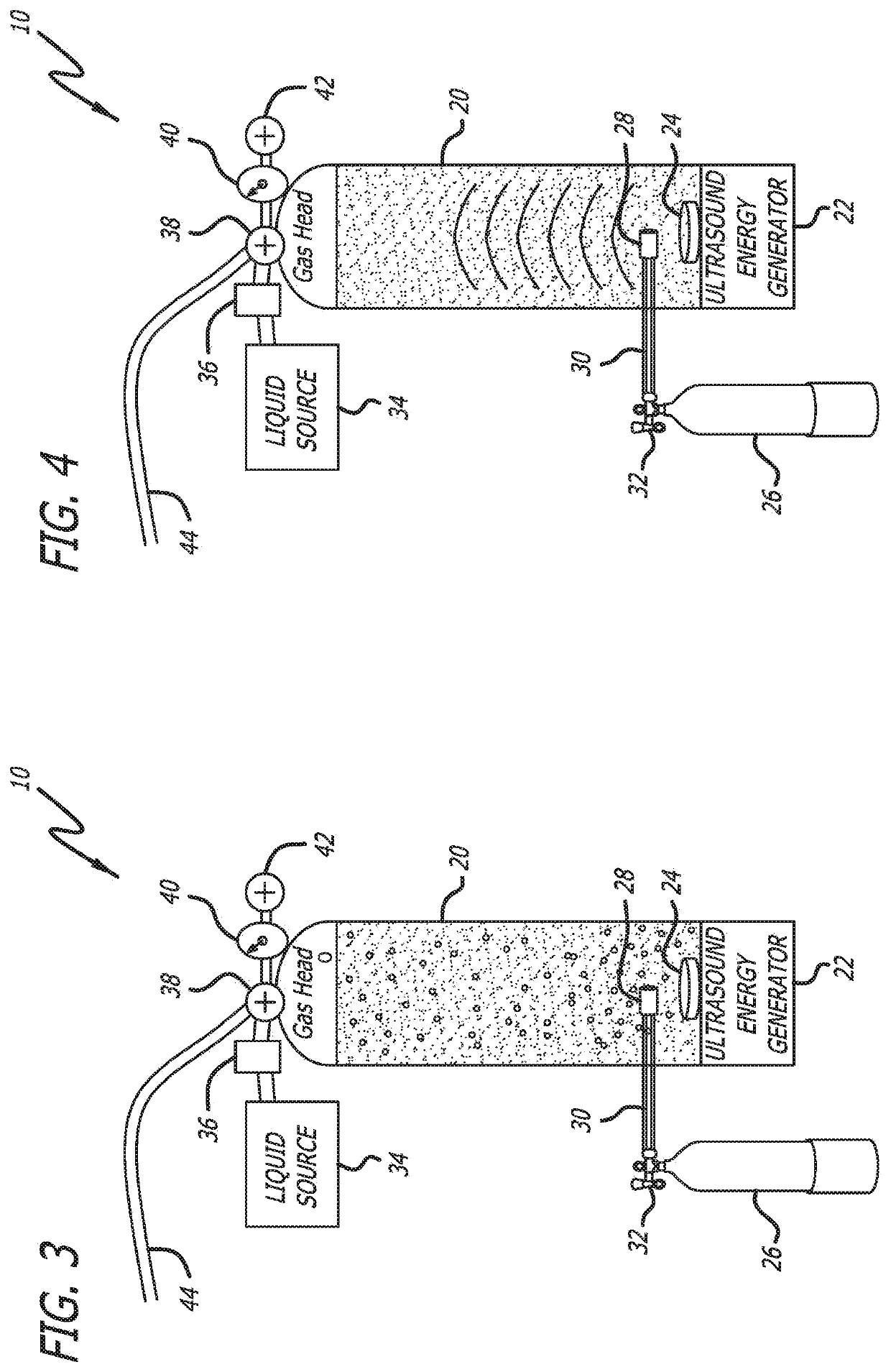
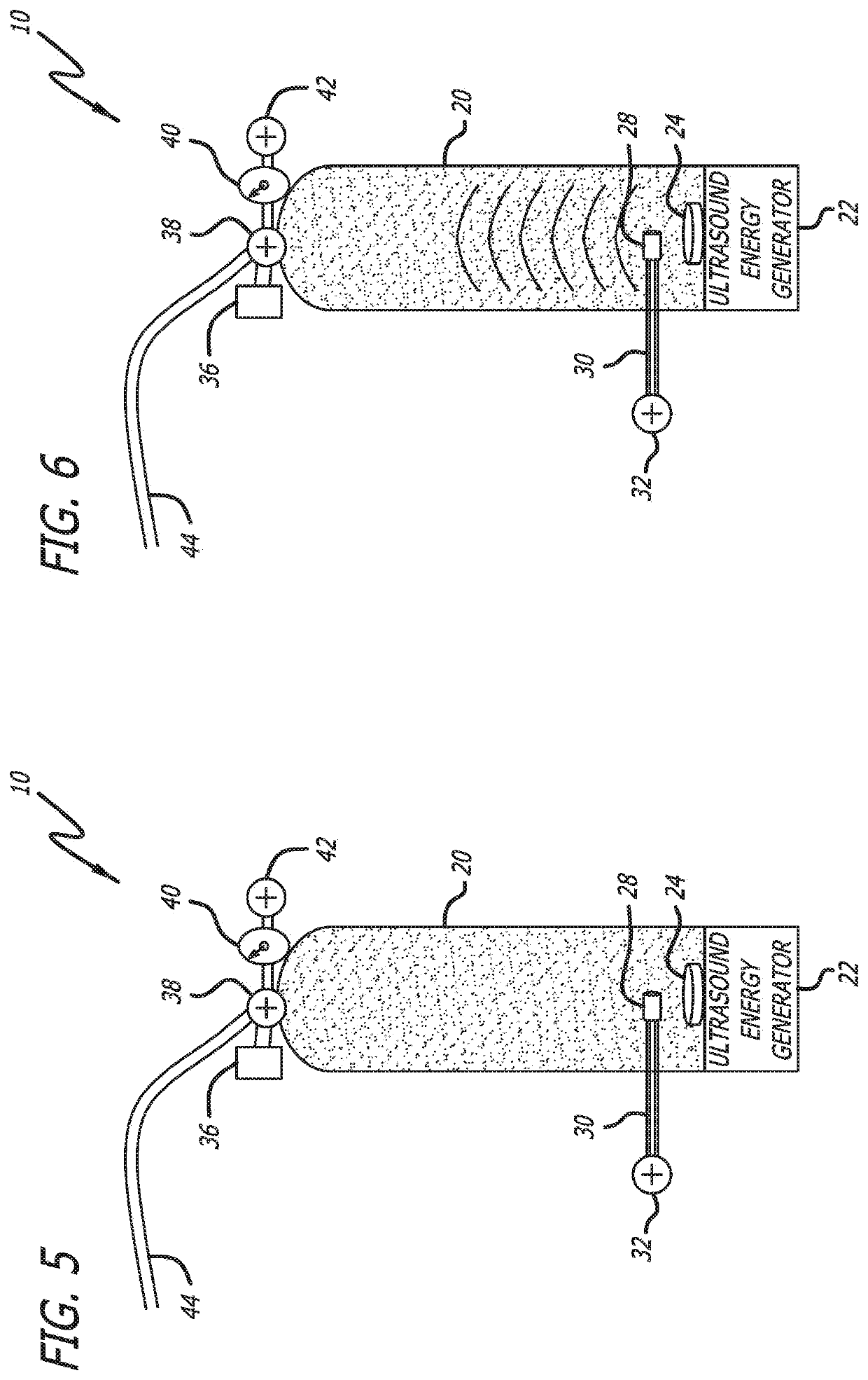
[0050]Embodiment 10 utilizes a tank 20 to prepare and store a nanobubble solution. The tank 20 contains within it an ultrasound energy generator 22. The ultrasound energy generator may utilize a piezoelectric ultrasound transducer 24. The system 10 also includes an oxygen source 26, such as an oxygen canister, connected to the tank 20 with oxygen supply tubing 30 via an oxygen supply valve 32. The oxygen tubing 30 passes into the tank 20 and terminates with an infusion gas diffuser 28. As used herein the term “infuser” refers to anything that introduces a gas into a liquid medium. A simple tube could thus be an infuser. A “diffuser”, as used herein, refers to a device attached to an infuser that reduces the size of the bubbles being introduced.
[0051]Also connected to the tank 20 is a liquid source 34. The liquid source 34 is shown as being connected to the tank 20 with a connector 36 and a three-way flow valve 38. In addition to the liquid source 34, the three-way flow valve 38 is a...
embodiment 200
[0065]Turning now to FIGS. 10-13, there is shown a continuous infusion embodiment 200 of an oxygenation device of the invention. This embodiment uses the patient's blood as the medium into which the oxygen is infused and ensonified. FIG. 10 shows the distal end of the device within a vein V of the patient to illustrate that the catheter is smaller than the vein, allowing room for the outflow of oxygenated blood from the sidewalls of the catheter. FIG. 11 shows the distal end of the device 200 without the vein to show the details of the device.
[0066]The device 200 includes a catheter 202 with a collapsible funnel 204 at one end that directs blood into the catheter 200. The catheter 202 has blood outflow holes 206 that allow the oxygenated blood to escape through the sidewalls of the catheter 202.
[0067]Within the catheter 202 is an oxygen infuser 208 connected to an oxygen inflow tube 210. Also within the catheter is an impeller pump 212 powered via pump power conductors 214. There is...
embodiment 230
[0073]FIG. 13 shows an embodiment 230 of a proximal end of the device 200. It can be seen an oxygen source 232 is connected to the proximal end of the oxygen inflow tube 210, which then enters into the proximal end of the catheter 202. There is also a motor controller 234 connected to the pump power conductors 214, and an ultrasound generator 236 attached to the piezo power conductors 220.
[0074]FIG. 14 shows an embodiment 250 of a proximal end of the device 200. This embodiment 250 has an ultrasound speaker 252, or other pulsating mechanism, that creates pressure pulses of the incoming gas so that the emission of gas bubbles occurs in pulses that limit the volume of bubble emitted with each pulse. An additional embodiment employs vibration of the emitting chamber, which has the effect of facilitating formation of small bubbles by causing them to break free of the surface of the emitter after a small gas bubble has formed on the outer surface. In another embodiment, a rotating member...
PUM
| Property | Measurement | Unit |
|---|---|---|
| diameters | aaaaa | aaaaa |
| diameter | aaaaa | aaaaa |
| diameter | aaaaa | aaaaa |
Abstract
Description
Claims
Application Information