Combustion chamber structure of engine

a combustion chamber and engine technology, applied in the direction of machines/engines, mechanical devices, non-fuel substance addition to fuel, etc., can solve the problems of difficulty in igniting the mixture gas by the spark plug and the water near the spark plug becoming higher

Active Publication Date: 2021-01-14
MAZDA MOTOR CORP
View PDF0 Cites 1 Cited by
  • Summary
  • Abstract
  • Description
  • Claims
  • Application Information

AI Technical Summary

Benefits of technology

[0006]The technology disclosed herein enables ignition of a...

Problems solved by technology

This is because a large amount of water has to be injected into the combustion chamber when increasing the engine torque.
That is, if the amount of water injected into ...

Method used


Image

  • Combustion chamber structure of engine
  • Combustion chamber structure of engine
  • Combustion chamber structure of engine

Examples


Embodiment Construction

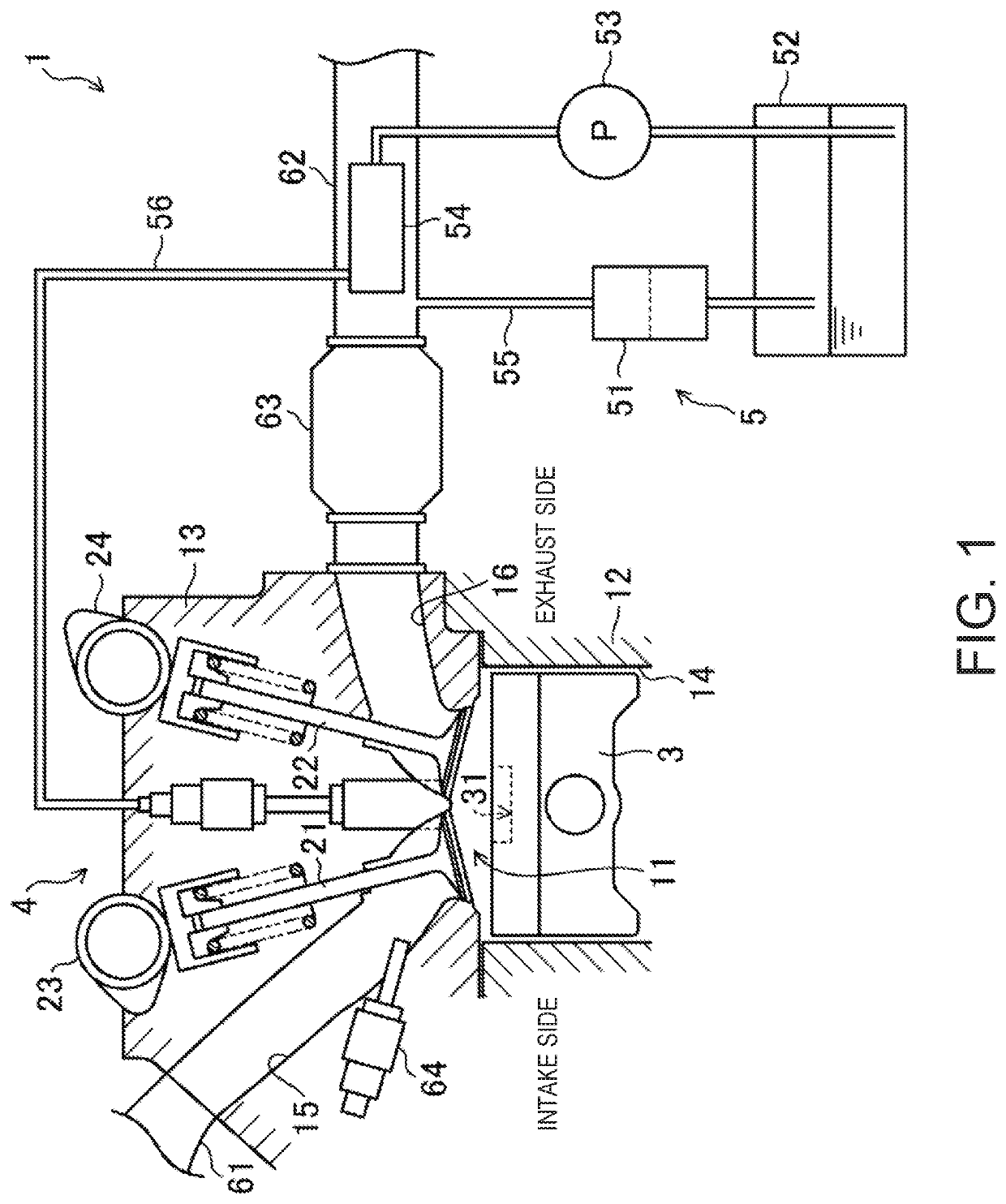
[0058]Hereinafter, one embodiment of a structure of a combustion chamber of an engine is described with reference to the accompanying drawings. The combustion chamber structure described herein is merely illustration.

[0059]FIG. 1 illustrates an engine 1 to which the combustion chamber structure disclosed herein is applied. The engine 1 is a four-stroke reciprocating engine which operates by a combustion chamber 11 repeating an intake stroke, a compression stroke, an expansion stroke, and an exhaust stroke. For example, the engine 1 is mounted on a four-wheel automobile. The automobile is propelled by the engine 1 operating. Fuel of the engine 1 is gasoline in this example. The fuel is liquidous fuel which at least includes gasoline. For example, the fuel may be gasoline which includes bioethanol.

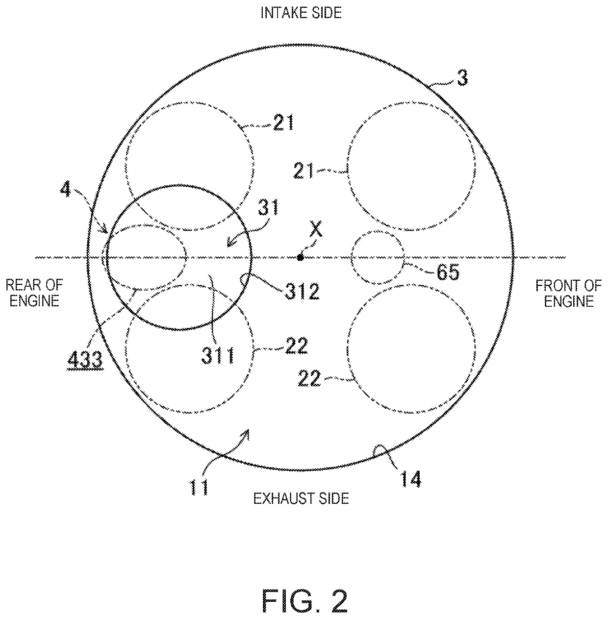
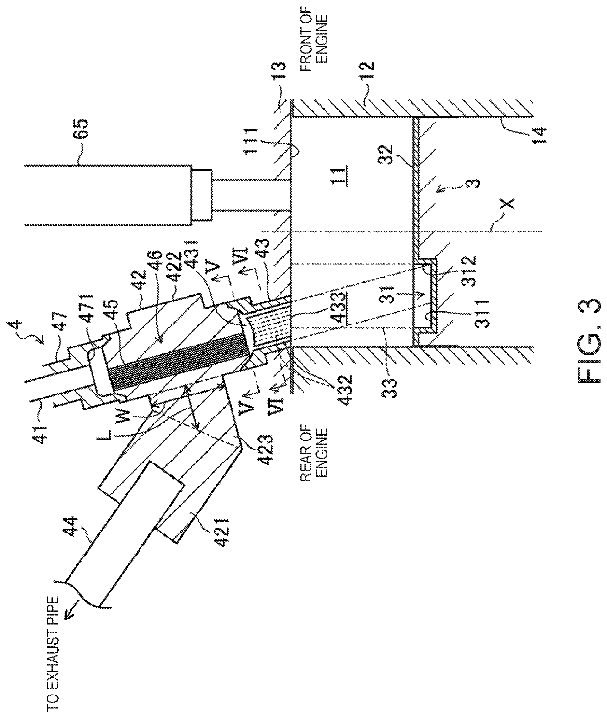
[0060]The engine 1 includes a cylinder block 12 and a cylinder head 13 placed on the cylinder block 12. A plurality of cylinders 14 are formed inside the cylinder block 12. The engine 1 is a...


PUM


Abstract

An engine system includes a combustion chamber including a cylinder formed in an engine and a piston configured to reciprocate inside the cylinder, a spark plug disposed in a ceiling part of the combustion chamber, and a water injection device configured to inject water into the combustion chamber through a plurality of nozzle holes facing the inside of the combustion chamber. The piston has a cavity in an upper surface thereof. The water injection device injects water into the cavity in a compression stroke at a timing when an extension of axes of at least some of the nozzle holes intersects the cavity. The cavity has a bottom part where the water injected by the water injection device collides, and a raising part configured to raise the water spreading along the bottom part toward the water injection device.

Description

TECHNICAL FIELD[0001]The technology disclosed herein relates to a combustion chamber structure of an engine.BACKGROUND OF THE DISCLOSURE[0002]JP6477849B1 discloses a compression ignition engine which combusts a portion of a mixture gas by compression ignition. This engine ignites the mixture gas by an ignition device. Flame propagation combustion begins, and unburnt mixture gas carries out self-ignition combustion by heat generated by the flame propagation combustion.[0003]The engine is provided with a water injection device which injects water into the combustion chamber. As the water injection device injects water into the combustion chamber, the inside of the combustion chamber is cooled. This engine can reduce the occurrence of abnormal combustion.[0004]In addition to the above-described purpose of reducing the abnormal combustion, the present inventors focused on an increase in an amount of operative gas by injecting the water (and steam) into the combustion chamber to increase...

Claims


Application Information

Patent Timeline
IPC IPC(8): F02B47/02F02M25/03F02M25/022
CPCF02B47/02F02M25/03F02B7/02F02M25/0224F02M25/0227F02B23/069Y02T10/12
Inventor NAGASAWAGE, XIYAOKAGEYAMA, AKIRAUCHIDA, HIROYASUKIYOSUE, RYO
Owner MAZDA MOTOR CORP
Why Eureka
Try Eureka