
Sintered bearing and method for manufacturing sintered bearing

a technology of sintered bearings and bearings, which is applied in the direction of sliding contact bearings, mechanical equipment, transportation and packaging, etc., can solve the problems of engine speed affecting the discharge quantity of cooling water, the inability to obtain power from an engine, and the inability to meet the requirements of the engine, so as to improve mechanical strength and vibration resistance. resistance, the effect of preventing the damage of the rotation sha

Active Publication Date: 2021-02-11
PORITE
View PDF0 Cites 2 Cited by
  • Summary
  • Abstract
  • Description
  • Claims
  • Application Information

AI Technical Summary

Benefits of technology

The present invention is related to a sintered bearing and its manufacturing method. This invention improves the mechanical strength and resistance to vibration of the bearing and prevents damage to the rotation shaft.

Problems solved by technology

For example, in conventional liquid pumps, since the power is obtained from an engine, there is a problem that a change in engine speed affects a discharge quantity of cooling water and cooling efficiency becomes unstable.
In particular, in a water pump mounted in a hybrid car, an electric-powered car, a fuel-cell car, or the like, the power cannot be obtained from an engine.
However, the bearing made of ceramics or carbon is excellent in the water resisting properties / corrosion resisting properties, but it has a problem of a high machining cost.
Moreover, the bearing made of resin has a problem that assuring a dimension accuracy is difficult and the load bearing properties are insufficient.
However, the sintered bearing has a problem in that it has poor water resisting properties / corrosion resisting properties and is not suitable for use in water.
In particular, when the sintered bearing is used in water, it has a problem that its sliding properties become insufficient.

Method used


Image

  • Sintered bearing and method for manufacturing sintered bearing
  • Sintered bearing and method for manufacturing sintered bearing
  • Sintered bearing and method for manufacturing sintered bearing

Examples


Embodiment Construction

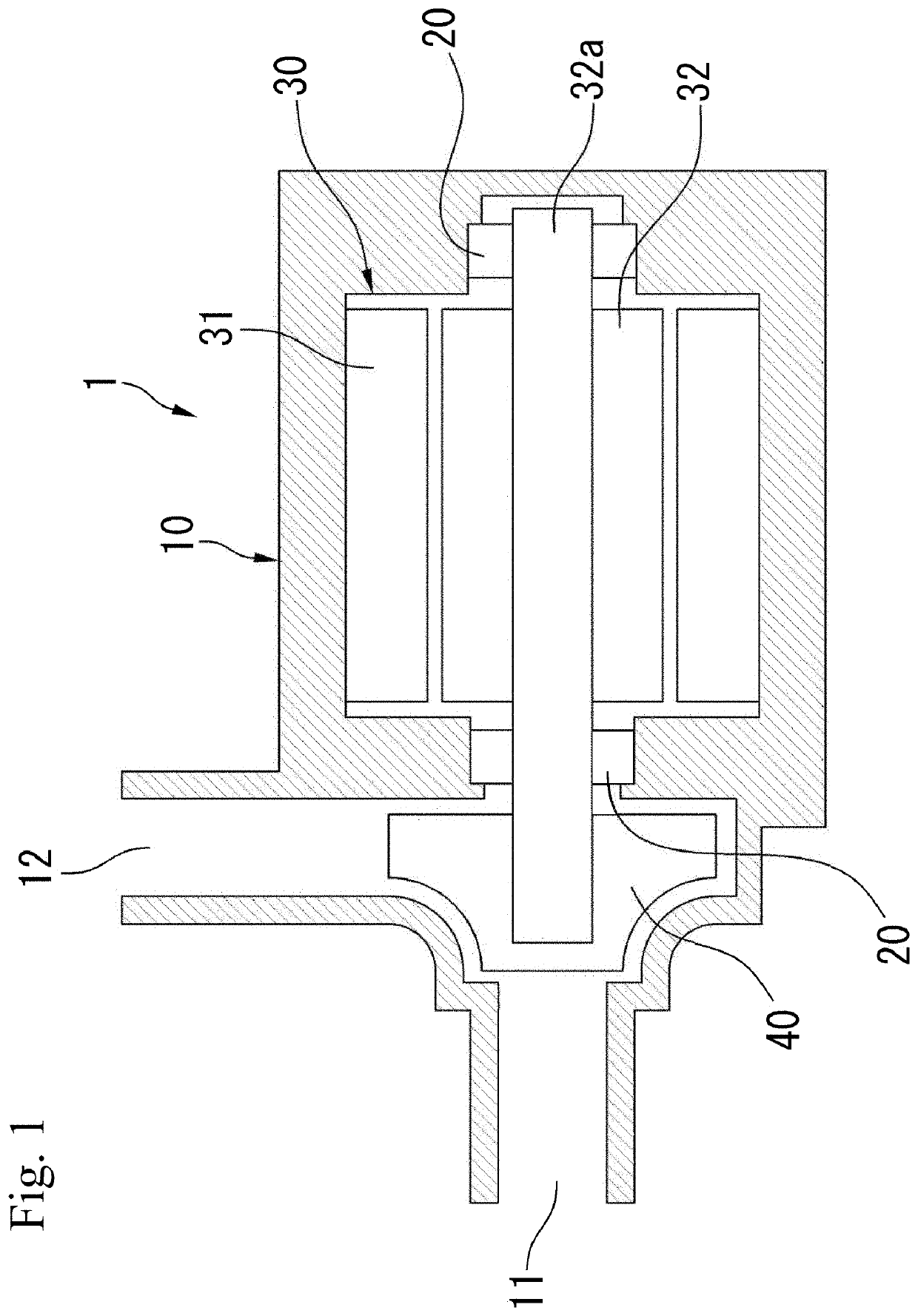
[0183]A description will now be given on examples of the present invention.

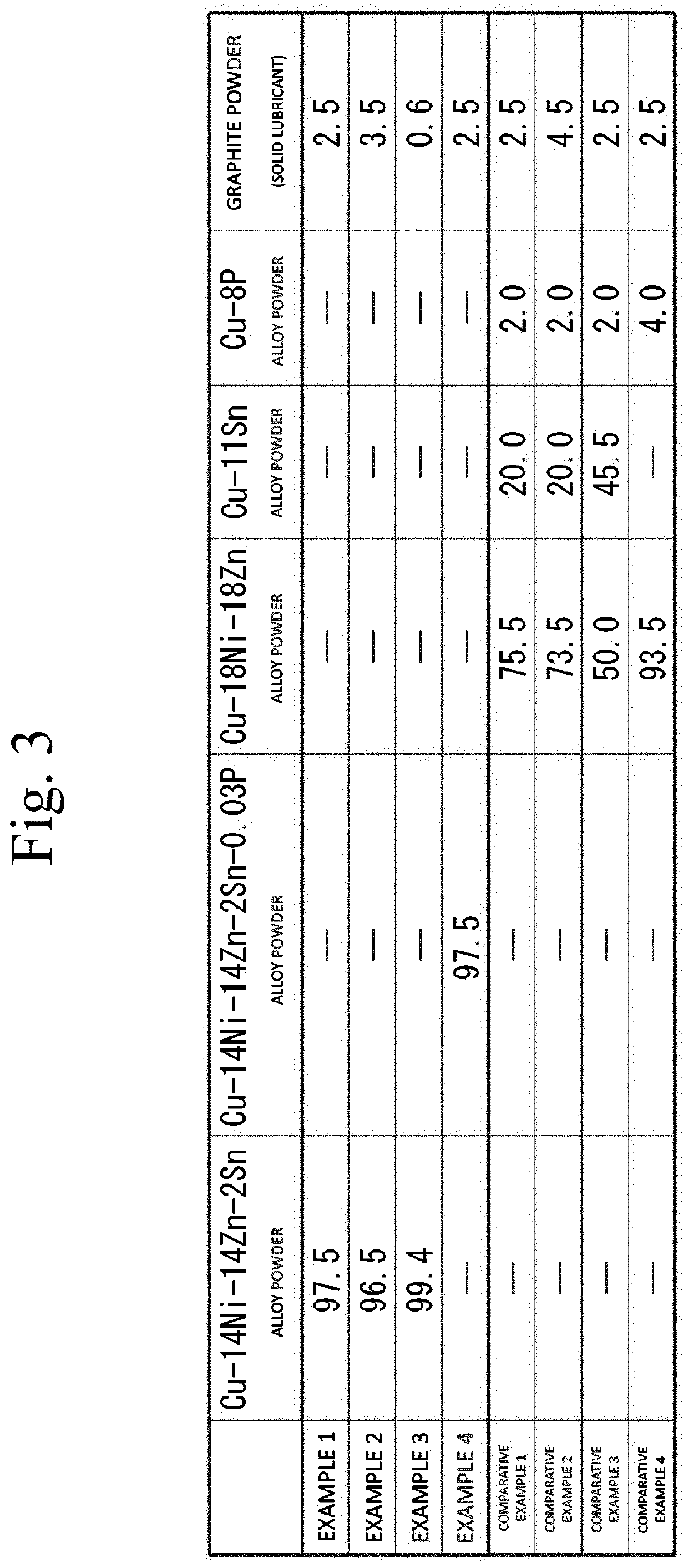
[0184]As examples of the present invention, four types of sintered bearings (Examples 1 to 4) were manufactured. Additionally, as comparative examples, four types of sintered bearings (Comparative Examples 1 to 4) were manufactured.

[0185]The sintered bearings according to Examples 1 to 4 were manufactured with the use of material powders having compositions according to the present invention. Consequently, the sintered compacts of the sintered bearings according to Examples 1 to 4 have the compositions according to the present invention.

[0186]That is, each of the sintered compacts of the sintered bearing according to Examples 1 to 3 has a composition containing, in terms of a mass ratio to a total mass of the material powder (the sintered compact), Ni which exceeds 10 mass % and is less than 20 mass %, Zn which exceeds 13 mass % and is less than 20 mass %, Sn which exceeds 0.5 mass % and is less than 3 mass %...


PUM

PropertyMeasurementUnit
crystal particle diameteraaaaaaaaaa
average crystal particle diameteraaaaaaaaaa
lengthaaaaaaaaaa

Abstract

A sintered bearing is made of a sintered compact containing nickel silver (Cu—Ni—Zn) as a base. In the sintered bearing, P is not added in the sintered compact. Alternatively, a content of P in the sintered compact is less than 0.05 mass % in terms of mass ratio to a total mass. Consequently, crystal grains constituting the sintered compact can be micronized. In particular, in the sintered bearing, an average crystal particle diameter of the crystal grains constituting the sintered compact is 20 μm or less. Consequently, the mechanical strength and the vibration resisting properties can be improved, and the rotation shaft can be prevented from being damaged.

Description

TECHNICAL FIELD[0001]The present invention relates to a sintered bearing and a method for manufacturing a sintered bearing, and more particularly to a sintered bearing suitable for application in a motor for a liquid pump and a method for manufacturing this sintered bearing.BACKGROUND ART[0002]As a liquid transportation pump (which will be referred to as a “liquid pump” hereinafter), various kinds of pumps have been known.[0003]For example, a liquid pump mounted in an automobile, a water pump configured to circulate cooling water for engine cooling, a washer liquid pump configured to discharge a window washer liquid, an oil pump configured to produce a hydraulic pressure in a hydraulic mechanism, an oil pump configured to pump an engine oil, a fuel pump configured to supply a fuel (gasoline, gas oil, alcohol, and others), or the like is known.[0004]In recent years, in view of stabilization of a discharge quantity (a pumpage), motorization of liquid pumps to obtain power from electri...

Claims


Application Information

Patent Timeline
Patent Type & Authority Applications(United States)
IPC IPC(8): F16C33/14F16C33/12B22F3/12B22F3/00B22F3/26
CPCF16C33/14F16C33/12B22F3/12B22F2301/10B22F3/26B22F2304/10B22F3/004B22F3/10B22F3/24C22C9/04C22C9/06C22C1/0425F16C33/121F16C33/128F16C33/145F16C33/1095F16C2204/10F16C2204/14F16C2240/48B22F5/106H02K7/083B22F2998/10B22F2999/00H02K7/14F16C33/104F16C2204/52F16C2360/42B22F3/1103B22F1/00B22F1/105B22F2003/166B22F3/02B22F5/00F16C17/02F16C33/10H02K7/08
Inventor TANABE, SHIGEYUKIASO, SHINOBUNARA, HIROSHI
Owner PORITE
Learn More