Hybrid electromagnetic transient simulation method for microgrid real-time simulation

a real-time simulation and hybrid technology, applied in the field of power systems, can solve the problems of large challenges to the realization of real-time simulation of the microgrid, the computation time of off-line simulation tools is far more than the duration of the transient, etc., and achieve the effects of improving the parallelity of the microgrid simulation, reducing the cost of real-time simulation, and improving the simulation efficiency of the microgrid

Active Publication Date: 2021-02-18
SHANGHAI JIAO TONG UNIV
View PDF0 Cites 6 Cited by
  • Summary
  • Abstract
  • Description
  • Claims
  • Application Information

AI Technical Summary

Benefits of technology

[0027](1) The traditional node analysis method (NAM) is combined with the highly parallel latency insertion method (LIM). The distribution network of the microgrid is simulated with the latency insertion method (LIM), which is called the LIM network, while the distributed power generation and converter systems is simulated with the node analysis method (NAM), which is called the NAM network. The LIM network and the plurality of NAM networks can be solved simultaneously, and the parallelism of the microgrid simulation is improved.
[0028](2) when the method of the present invention is used for carrying out real-time simulation of the microgrid, the calculation speed is higher than that of the traditional node analysis method, and the simulation efficiency of the microgrid real-time simulation is greatly improved. In the traditional node analysis method, the inverse of the coefficient matrix in the node voltage equation is a high-order off-diagonal matrix, where the calculation amount is in quadratic proportion to the number of nodes. In the method of the present invention, all coefficient matrixes of the LIM network are diagonal matrixes, and all coefficient matrixes of the NAM network are low-order off-diagonal matrixes, so that the calculation burden occurred when the traditional node analysis method is used for solving large-scale network equations is avoided. The total calculation amount of the method of the present invention is smaller than that of the traditional node analysis method and is linearly proportional to the simulation scale, and the real-time simulation efficiency is improved.
[0029](3) On Kintex-7 410T FPGA chip from XILINX, real-time simulation is carried out on a microgrid consisting of 3 three-phase inverters, 3 Boost circuits and 21 three-phase lines using both the method of the present invention and the traditional node analysis method. According to the method of the present invention, the simulation time-step of 380 ns can be adopted at the minimum, and hardware resources of the FPGA are consumed as follows: look-up table 49.6%, flip-flop 48.8%, RAM block 12.2%, DSP48 multiplier 63.1%. In the traditional node analysis method, the simulation time-step of 1970 ns can be adopted at the minimum, and various hardware resources of the FPGA are consumed as follows: look-up table 81.8%, flip-flop 76.7%, RAM block 12.2%, DSP48 multiplier will exceed 100% and the microgrid real-time simulation cannot be completed. Therefore, the method of the present invention can realize smaller simulation time-step and larger simulation scale on the FPGA, so that the microgrid real-time simulation capability based on the FPGA is improved, and the method of the present invention is very suitable for submicrosecond real-time simulation of the microgrid containing a plurality of power electronic converters and a large number of power distribution lines.

Problems solved by technology

In general, off-line simulation tools take far more computation time than the duration of the transient phenomena under study.
There are many AC / DC or DC / DC converters in the microgrid, and the high-frequency switching characteristics of power electronic switches bring great challenges to the realization of real-time simulation of the microgrid.

Method used


Image

  • Hybrid electromagnetic transient simulation method for microgrid real-time simulation
  • Hybrid electromagnetic transient simulation method for microgrid real-time simulation
  • Hybrid electromagnetic transient simulation method for microgrid real-time simulation

Examples


Embodiment Construction

[0036]The present invention is further explained below with reference to the figures and embodiments.

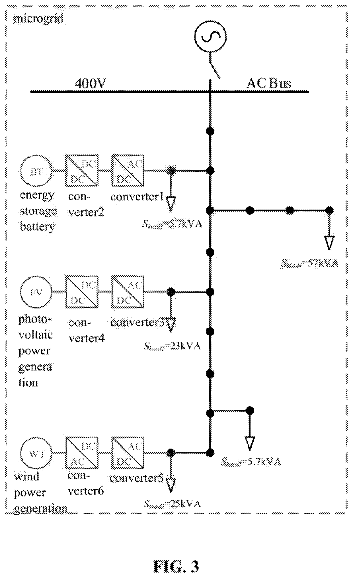
[0037]As shown in FIG. 3, a microgrid comprising 3 three-phase inverters, 3 circuits, and 21 three-phase lines is taken as an example to illustrate the present invention, but the protection scope of the present invention should not be limited thereby.

[0038]When the hybrid electromagnetic transient simulation method suitable for microgrid real-time simulation is applied to real-time simulation of the microgrid, the hardware part mainly comprises: (1) PXIe controller (product model: PXIe-8135) from National Instruments (NI): being mainly responsible for the simulation of a microgrid control system, being able to communicate with a host computer through an Ethernet, and displaying real-time simulation waveforms on the upper computer; and (2) FPGA module (model: PXIe-7975R, built in a Kintex-7 410T FPGA chip from XILINX) from National Instruments (NI): being mainly responsible for the si...


PUM


Abstract

A hybrid electromagnetic transient simulation method for microgrid real-time simulation, wherein a traditional node analysis method (NAM) and a highly parallel latency insertion method (LIM) are combined, so that the microgrid is firstly divided from a filter of a distributed power generation system to form one latency insertion method (LIM) network containing a power distribution line and a plurality of node analysis method (NAM) networks containing the distributed power generation system respectively, the NAM network being simulated by traditional node analysis method, the LIM network being simulated by the latency insertion method, in an initialization stage, one correlation matrix and four diagonal matrixes containing line parameters used for LIM network simulation being formed according to line topology and parameters of the microgrid, in a main cycle of the simulation, the LIM network solved simultaneously with multiple NAM networks, a parallelism of a microgrid simulation being improved.

Description

CROSS-REFERENCE TO RELATED APPLICATIONS[0001]The subject application is a continuation of PCT / CN2019 / 106095 filed on Sep. 17, 2019, which claims priority on Chinese Application No. CN201910756536.9 filed on Aug. 16, 2019 in China. The contents and subject matter of the PCT international application and Chinese priority application are incorporated herein by reference.TECHNICAL FIELD[0002]The present invention relates to power system, in particular, a hybrid electromagnetic transient simulation method suitable for microgrid real-time simulation.BACKGROUND ART[0003]A microgrid is used for energy management of new energy access in the power distribution network. Before the practical application of the microgrid, the hardware-in-loop test, which is based on electromagnetic transient simulation, is needed for its controller, protection device, and control strategy.[0004]H. W. Dommel of Canada proposed the basic theory and method of electromagnetic transient simulation in the late 1960s. ...

Claims


Application Information

Patent Timeline
Patent Type & Authority Applications(United States)
IPC IPC(8): H02J3/00H02J3/38
CPCH02J3/004H02J2203/20H02J3/381H02J3/00125Y04S40/20Y02E60/00
Inventor WANG, KEYOUXU, JINLI, GUOJIELI, ZIRUNWU, PAN
Owner SHANGHAI JIAO TONG UNIV
Why Eureka
Try Eureka