Process for the Synthesis of Fluorinated Conductive Salts for Lithium Ion Batteries

a technology of lithium ion batteries and conductive salts, which is applied in the field of lithium ion battery fluorinated conductive salt synthesis, can solve the problems of difficulty in fluorination, published synthesis methods, and no economic synthesis, and achieves the effect of reducing and simplifying avoiding time and energy consumption, and reducing the number of separation steps

Pending Publication Date: 2021-02-25
FUJIAN YONGJING TECH CO LTD
View PDF0 Cites 2 Cited by
  • Summary
  • Abstract
  • Description
  • Claims
  • Application Information

AI Technical Summary

Benefits of technology

[0125]A very particular advantage of the present invention employing a microreactor, or a continuous flow reactor with the before said lateral dimensions, the number of separating steps can be reduced and simplified, and may be devoid of time and energy consuming, e.g. intermediate, distillation steps. Especially, it is a particular advantage of the present invention employing a microreactor, or a continuous flow reactor with the before said lateral dimensions, that for separating simply phase separation methods can be employed, and the non-consumed reaction components may be recycled into the process, or otherwise be used as a product itself, as applicable or desired.
[0126]In addition to the preferred embodiments of the present invention using a microreactor according to the invention, in addition or alternatively to using a microreactor, it is also possible to employ a plug flow reactor or a tubular flow reactor, respectively.
[0127]Plug flow reactor or tubular flow reactor, respectively, and their operation conditions, are well known to those skilled in the field.
[0128]Although the use of a continuous flow reactor with upper lateral dimensions of about ≤5 mm, or of about ≤4 mm, respectively, and in particular of a microreactor, is particularly preferred in the present invention, depending on the circumstances, it could be imagined that somebody dispenses with an microreactor, then of course with yield losses and higher residence time, higher temperature, and instead takes a plug flow reactor or turbulent flow reactor, respectively. However, this could have a potential advantage, taking note of the mentioned possibly disadvantageous yield losses, namely the advantage that the probability of possible blockages (tar particle formation by non-ideal driving style) could be reduced because the diameters of the tubes or channels of a plug flow reactor are greater than those of a microreactor.
[0129]The possibly allegeable disadvantage of this variant using a plug flow reactor or a tubular flow reactor, however, may also be seen only as subjective point of view, but on the other hand under certain process constraints in a region or at a production facility may still be appropriate, and loss of yields be considered of less importance or even being acceptable in view of other advantages or avoidance of constraints.
[0130]In the following, the invention is more particularly described in the context of using a microreactor. Preferentially, a microreactor used according to the invention is a ceramic continuous flow reactor, more preferably an SiC (silicon carbide) continuous flow reactor, and can be used for material production at a multi-to scale. Within integrated heat exchangers and SiC materials of construction, it gives optimal control of challenging flow chemistry application. The compact, modular construction of the flow production reactor enables, advantageously for: long term flexibility towards different process types; access to a range of production volumes (5 to 400 l / h); intensified chemical production where space is limited; unrivalled chemical compatibility and thermal control.

Problems solved by technology

As of today, there are several published synthesis methods but none of them allow economic synthesis which would allow large industrial scale production.
In Lonza's and Nippon Shokubai's application, challenging fluorination has to happen in late stage.
If this late stage fluorination step is done with a fluorinating agent and NOT with HF or F2 etc. which need NO carrier of the “F”-atom (fluorinating agents always have a part of the molecule which need to be incinerated or at least which is very difficult to recycle), besides selectivity, purification is difficult, challenging or even impossible in view to economics.
Using KF (or other metal fluorides “look” simple on first view, but as reactivity of such metal fluorides strongly depends on necessary dipolar aprotic solvents often in presence of crown ethers, ionic liquids or phase transfer catalysts etc. which cannot or only very difficult be separated from desired products.

Method used


Image

  • Process for the Synthesis of Fluorinated Conductive Salts for Lithium Ion Batteries
  • Process for the Synthesis of Fluorinated Conductive Salts for Lithium Ion Batteries
  • Process for the Synthesis of Fluorinated Conductive Salts for Lithium Ion Batteries

Examples


example 1

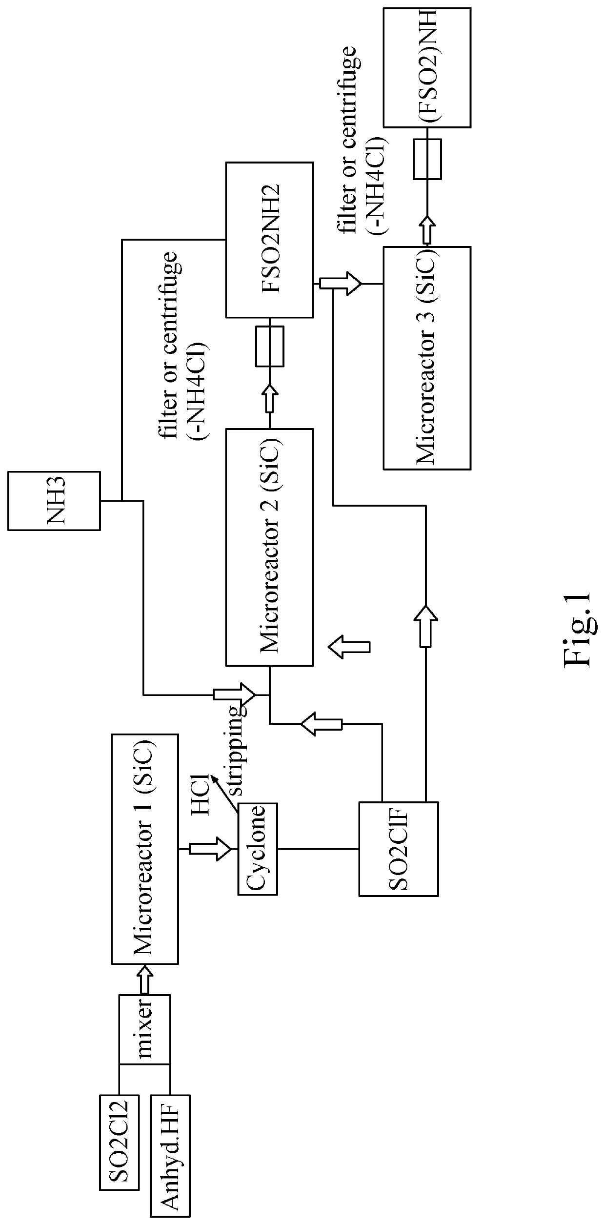
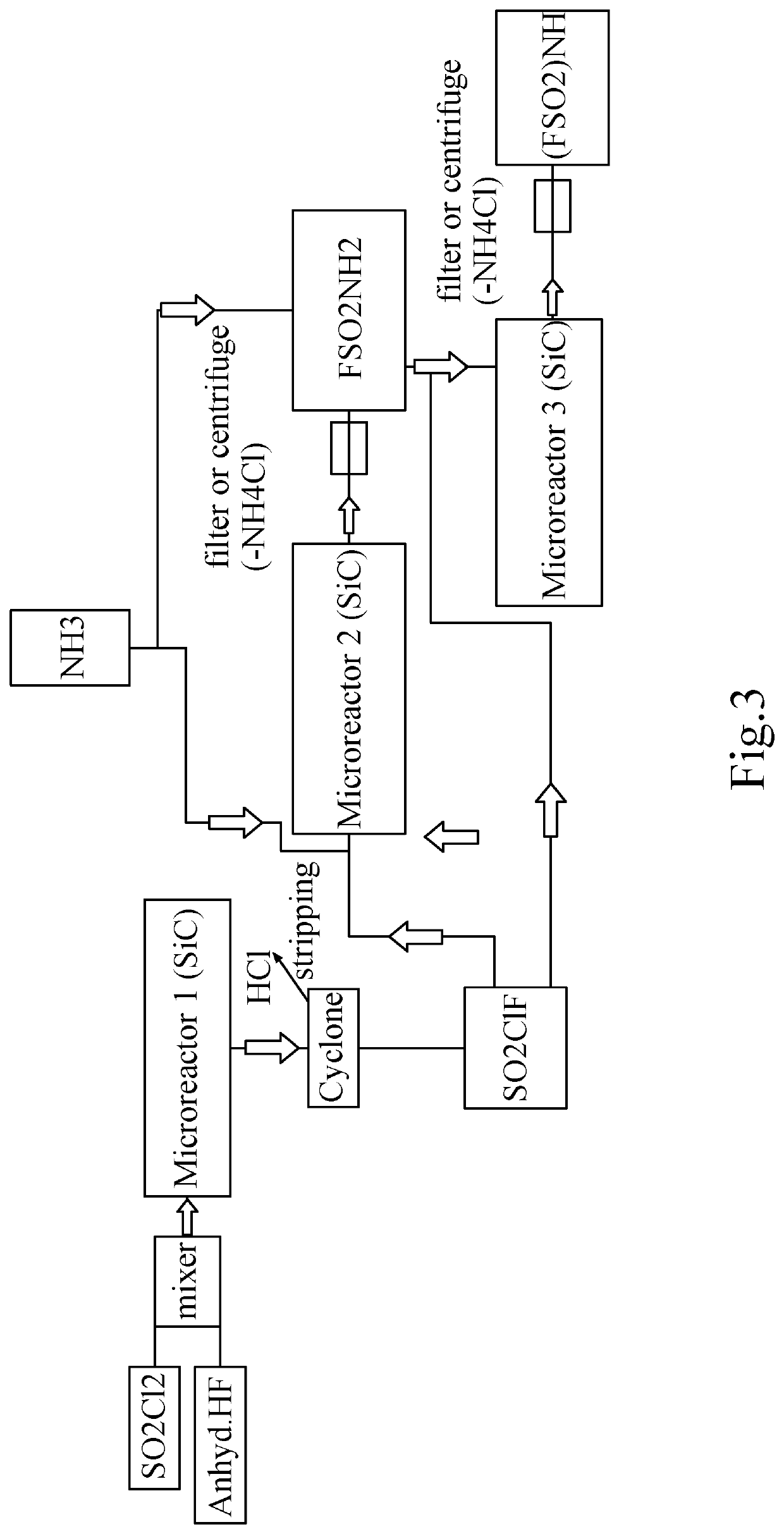
[0186]Synthesis of SO2ClF without catalyst and without any presence of a fluorinating agent.

[0187]SO2ClF is synthesized in batch by adding HF (anhydreous) into SO2Cl2, e.g., in a Roth autoclave with HDPTFE Inliner, 1 deep pipe and one outlet at gas phase (pressure kept at 10 bar) at room temperature (without any catalyst under evolvement of HCl or continuously in a microreactor system). So 110 g (0.82 mol) Sulfurylchlorid is filled into a 250 ml Autoclave (company Roth) having a HPTFE Inliner, after closing of the autoclave, 82.1 g (4.1 mol) anhydrous HF was added from a N2 pressurized Cylinder from the liquid phase over the deep pipe into the autoclave. The autoclave is then slowly heated to 50° C. with an oil bath (pressure kept at 10 bar) and formed HCl is let escape into a scrubber over a pressure valve.

[0188]After 99.9% of the HCl has left the autoclave (calculated by analysis of Chloride in the scrubber), the remaining content (which is almost 100% SO2ClF+HF) is transferred in...

example 2

[0189]Conversion of SO2ClF to FSO2NH2.

[0190]To the autoclave content which was 90 g (0.77 mol) as prepared under example 1, 32.4 g (1.9 mol) NH3 is now fed into the autoclave. The mixture is let to warm up and the reaction is finalized by keeping further 3 h at 50° C. The autoclave is cooled to room temperature, remaining pressure released into a scrubber and afterwards, the formed Ammoniumchloride is filtered off the formed Fluorosulfonylamide to get finally a yellow to brownisch liquid which is FSO2NH2 (97% purity (GC)).

[0191]Remark: As SO2ClF is much more reactive than SO2Cl2, the conversion to the isocyanate by using hazardous chemicals like in other literature references can be avoided and saved.

example 3

[0192]Conversion of FSO2NH2 to FSO2NHSO2F.

[0193]In the next step, added to the Fluorosulfonamide of example 2, is a 1.01 stöchiometric amount of another ClSO2F (prepared according to example 1) followed by a 1.01 stöchiometric amount of NH3 which is kept together at 50° C. for 2 h. After cooling down and expanding to atmospheric pressure, the formed NH4Cl is filtered off again. A brown solid is isolated which is characterized as Bis-Fluorosulfonylimide. Other easier than NH3 to handle bases like NEt3, DBN, DBU, DMAP, Pyridine are also possible or could be added as accelerator but this alternatives are more difficult to be separated from the product.


PUM

PropertyMeasurementUnit
residence timeaaaaaaaaaa
flow rateaaaaaaaaaa
temperatureaaaaaaaaaa

Abstract

The invention relates to a new process for the synthesis of fluorinated conductive salts for lithium ion batteries (Li-ion batteries). The said fluorinated conductive lithium ion (Li-ion) battery salts of interest in the framework of the present inventions synthesis process, for example, are Li-ion salts such as LiFSI (lithium bis-(fluoromethanesulfonlyl) imide), LiTFSI (lithium bis-(trifluormethanesulfonlyl) imide), and LiTFSFI (lithium trifluoromethanesulfonylfluorosulfonyl imide), with the formulas as displayed in the Table I herein below. LiFSI, LiTFSI and LiFSTFSI are the most promising conducting salts for Lithium ion batteries and essential for future electromobility.

Description

BACKGROUND OF THE INVENTIONField of the Disclosure[0001]The invention relates to a new process for the synthesis of fluorinated conductive salts for lithium ion batteries (Li-ion batteries). The said fluorinated conductive lithium ion (Li-ion) battery salts of interest in the framework of the present inventions synthesis process, for example, are Li-ion salts such as LiFSI (lithium bis-(fluoromethanesulfonlyl) imide), LiTFSI (lithium bis-(trifluormethanesulfonlyl)imide), and LiTFSFI (lithium trifluoromethanesulfonylfluorosulfonylimide), with the formulas as displayed in the Table I herein below.Description of Related Art[0002]LiFSI, LiTFSI and LiFSTFSI are the most promising conducting salts for Lithium ion batteries and essential for future electromobility as commonly used conducting salts like LiPF6 have drawbacks regarding stability and as consequence regarding safety of a battery. High purities of 99.9% or even higher are necessary to achieve high live time and many re-charging ...

Claims


Application Information

Patent Timeline
Patent Type & Authority Applications(United States)
IPC IPC(8): C07C303/38H01M10/0525C01B21/093H01M4/58H01M4/60B01J19/00
CPCC07C303/38H01M10/0525C01B21/0935C07C311/48H01M4/60B01J19/0093H01M4/58C07C303/40H01M4/582C01B21/086C07C303/36Y02E60/10C07C311/39
Inventor ZHOU, CHANGYUEDU, HONGJUNWU, WENTING
Owner FUJIAN YONGJING TECH CO LTD
Why Eureka
Try Eureka