Nuclear materials apparatus and implementing the same

a technology for nuclear fuel and apparatus, applied in nuclear engineering, nuclear elements, greenhouse gas reduction, etc., can solve the problems of reducing the capacity of the basket relative to the non-flux trap basket, reducing the thickness of the basket, and reducing the thickness without additional modification, so as to increase the structural strength of the basket. the effect of the apparatus

Active Publication Date: 2021-02-25
HOLTEC INT
View PDF10 Cites 4 Cited by
  • Summary
  • Abstract
  • Description
  • Claims
  • Application Information

AI Technical Summary

Benefits of technology

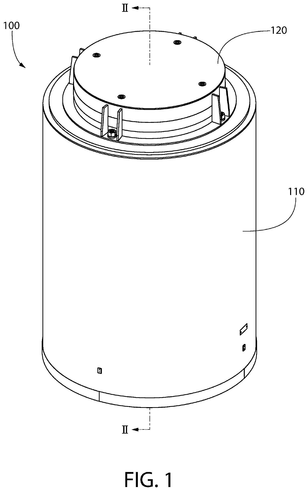
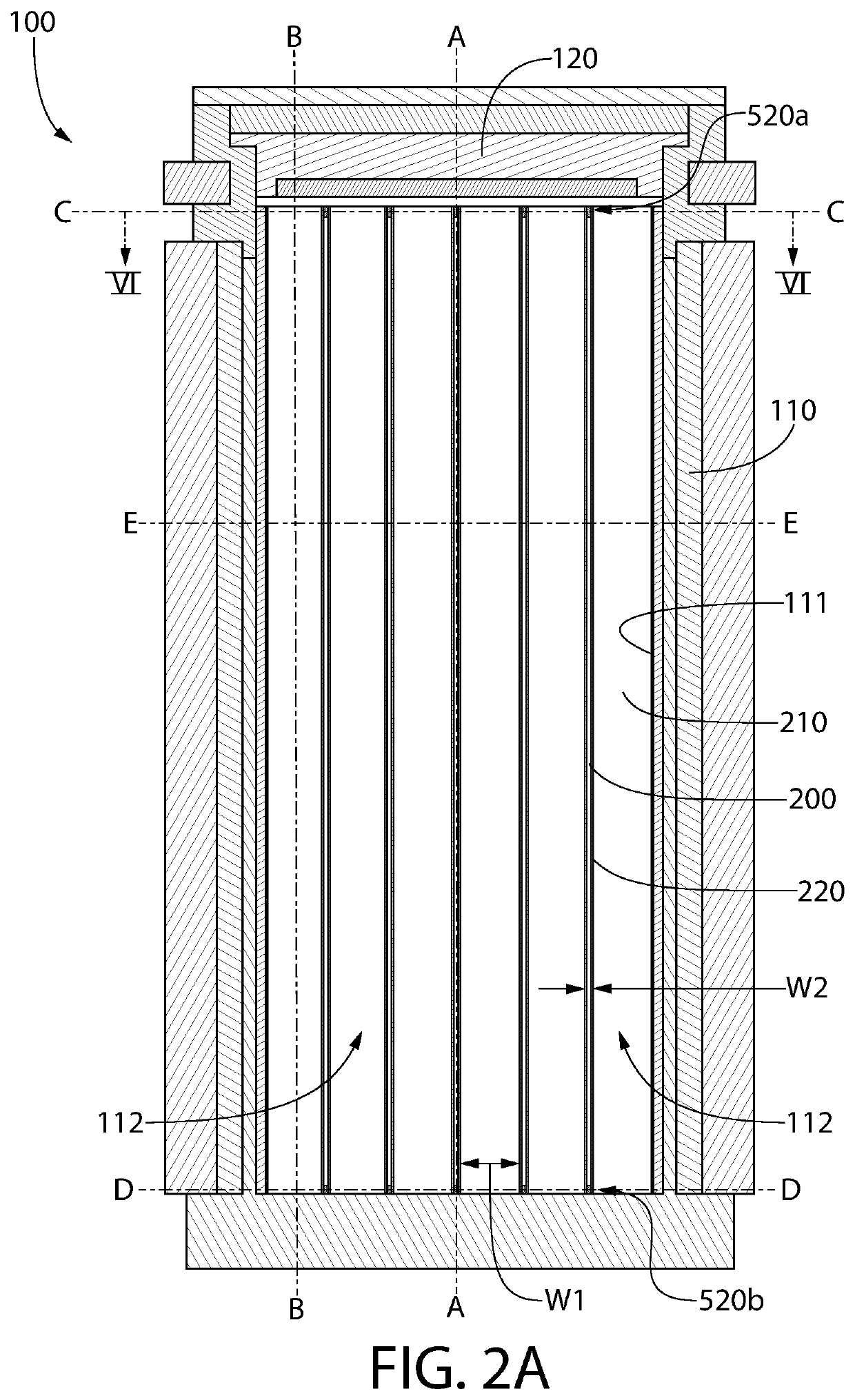
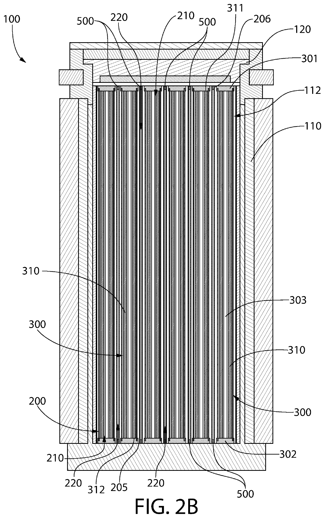
[0037]The present application is directed to an apparatus for supporting spent nuclear fuel. The apparatus may include a basket apparatus that is designed to be inserted into a cavity of a container. The basket apparatus may be formed by arranging a plurality of slotted plates in an intersecting manner, although other designs for the basket apparatus that do not include use of such slotted plates may also be used to form the basket apparatus. The slotted plates may form fuel cells for storing fuel assemblies with spent nuclear fuel rods therein and flux trap spaces between adjacent ones of the fuel cells. Furthermore, the apparatus may include reinforcement members positioned in the flux traps to increase the structural strength of the basket apparatus.

Problems solved by technology

Flux trap baskets require an additional empty space between each fuel cell, which results in the flux trap baskets having a reduced capacity relative to non-flux trap baskets.
Thus, there is great hesitancy in the industry to reduce the material thickness, and in fact such thickness reductions without additional modification may not pass required agency approvals.
Upon removal, the spent nuclear fuel (hereinafter, “SNF”) is still highly radioactive and produces considerable heat, requiring that great care be taken in its packaging, transporting, and storing.
This projection, however, is a problem where the cask must be designed to withstand a free fall event such as that required for transport casks containing used nuclear fuel.
The projection of the trunnion, made of a high strength steel or other alloy material, however, interferes with the crushing action of the impact limiter if the impact orientation of the cask is aligned with the plane of the trunnion.
The above limitations make the conventional trunnion design a rather unsatisfactory embodiment.
Upon removal, this spent nuclear fuel (“SNF”) is still highly radioactive and produces considerable heat, requiring that great care be taken in its packaging, transporting, and storing.
Stress Corrosion Cracking (SCC) of stainless steel nuclear waste canisters and containers in storage at costal sites with harsh marine environments is an important issue receiving increased industry and regulatory scrutiny.
This means that if there is a sufficient amount of decay heat available, only a short lowermost region of the vertical canister and the bottom half of the horizontal canister are vulnerable to Stress Corrosion Cracking (hereinafter, “SCC”); the balance of the canister is not.
The problem arises, however, when the decay heat progressively declines with the passage of time, the heating of air becomes much slower making a greater portion of the canister vulnerable to SCC.
The spent nuclear fuel (“SNF”) in the fuel assemblies is still highly radioactive and produces considerable heat which must be dissipated, in addition to concomitantly emitting dangerous ionizing neutron and gamma photons (i.e. neutron and gamma radiation) requiring protective shielding.
These boron-containing materials however are not effective at attenuating and shielding gamma radiation emitted from the fuel baskets.
Heretofore, spent nuclear fuel baskets have not addressed the issue of gamma radiation shielding.
Some peripheral clearance in the storage cell is also typically required to accommodate a damaged fuel assembly that has been physically damaged and is no longer in-tact for normal handling.
The spent nuclear fuel (“SNF”) in the fuel assemblies is still highly radioactive and produces considerable heat which must be dissipated, in addition to concomitantly emitting dangerous ionizing neutron and gamma photons (i.e. neutron and gamma radiation) requiring protective shielding.
These boron-containing materials however are not effective at attenuating and shielding gamma radiation emitted from the fuel baskets.
Such a cask body made with high-density conductive materials has excellent heat conduction and gamma radiation shielding capabilities, but unfortunately possesses a relatively modest neutron capture capability.
This traditional transfer cask design suffers from several drawbacks which makes it marginal or unsuitable for loading canisters with high decay heat generation rates (i.e., in excess of 40 kW), in locations where the crane capacity is less than what is typically needed to load such a heavy transfer cask with inserted canister, or where the facility's cask loading area dimensions or spatial constraints prevent the placement of a traditional large-sized high-capacity transfer cask.
In addition to emitting dangerous ionizing neutron and gamma photons (i.e. neutron and gamma radiation) requiring protective shielding, the highly radioactive SNF in the fuel assemblies still produces considerable heat which must be dissipated to avoid damage to the fuel assemblies.
Cooling of conventional ventilated modules suffers from several drawbacks.
The cooling air inlets are typically close to the support pad and susceptible to blockage by snow, debris, or runoff and floor waters at outdoor flood prone sites.
In unsheltered locations, the variability in wind direction with respect to the location of cooling air inlet and outlet duct locations may adversely impact the air flow rate and cooling of the fuel assemblies.
This adversely affects cooling performance and efficiency resulting in inadequate cooling of the fuel assemblies held inside the outer storage module.

Method used


Image

  • Nuclear materials apparatus and implementing the same
  • Nuclear materials apparatus and implementing the same
  • Nuclear materials apparatus and implementing the same

Examples


Embodiment Construction

[0197]The features and benefits of the invention are illustrated and described herein by reference to exemplary embodiments. This description of exemplary embodiments is intended to be read in connection with the accompanying drawings, which are to be considered part of the entire written description. Accordingly, the disclosure expressly should not be limited to such exemplary embodiments illustrating some possible non-limiting combination of features that may exist alone or in other combinations of features.

[0198]In the description of embodiments disclosed herein, any reference to direction or orientation is merely intended for convenience of description and is not intended in any way to limit the scope of the present invention. Relative terms such as “lower,”“upper,”“horizontal,”“vertical,”, “above,”“below,”“up,”“down,”“top” and “bottom” as well as derivatives thereof (e.g., “horizontally,”“downwardly,”“upwardly,” etc.) should be construed to refer to the orientation as then desc...


PUM


Abstract

An apparatus for supporting spent nuclear fuel including a plurality of wall plates arranged in an intersecting manner to define a basket apparatus extending along a longitudinal axis. The basket apparatus may include a plurality of fuel cells and a plurality of flux traps between adjacent fuel cells. A plurality of reinforcement members may be positioned in the flux traps and may extend between opposing ones of the wall plates that form the flux traps. Each of the wall plates may be a slotted wall plate. The slotted wall plates may be interlocked with one another to form the basket apparatus. Each of the slotted wall plates may include an upper edge, a lower edge, and a plurality of plate slots formed in each of the upper and lower edges. The plate slots of the slotted wall plates may receive intersecting slotted wall plates.

Description

CROSS-REFERENCE TO RELATED APPLICATIONS[0001]This application is a continuation-in-part of U.S. patent application Ser. No. 15 / 570,790, filed Oct. 31, 2017, which is a U.S. national stage application under 35 U.S.C. § 371 of PCT Application No. PCT / US2016 / 030809, filed May 4, 2016, which claims the benefit of U.S. Provisional Application No. 62 / 156,604, filed May 4, 2015. The entireties of the foregoing applications are incorporated herein by reference.[0002]This application is also a continuation-in-part of U.S. patent application Ser. No. 16 / 690,228, filed Nov. 21, 2019, which is a continuation of U.S. patent application Ser. No. 16 / 086,961, filed Sep. 20, 2018, (now U.S. Pat. No. 10,515,730), which is a U.S. national stage application under 35 U.S.C. § 371 of PCT Application No. PCT / US2017 / 022648, filed Mar. 16, 2017, which claims the benefit of U.S. Provisional Patent Application Ser. No. 62 / 311,540, filed Mar. 22, 2016. The entireties of the foregoing applications are incorpora...

Claims


Application Information

Patent Timeline
Patent Type & Authority Applications(United States)
IPC IPC(8): G21F5/005G21F5/08G21F5/10G21F5/12G21F9/34
CPCG21F5/005G21F5/08G21F9/34G21F5/12G21F5/10G21F5/012G21F5/14G21C19/40Y02E30/30
Inventor SINGH, KRISHNA P.ANTON, P. STEFANSPRINGMAN, RICHARD M.MAHORTER, ROBERT
Owner HOLTEC INT
Why Eureka
Try Eureka