
Eureka
For R&D, Eureka makes reading and utilizing patents & technical documents easy.
Eureka AIR
Designed for self-driven R&D workflows. Generate viable solutions, solve complex R&D challenges, empower your innovation with AI.

Eureka Materials
Designed for material experts only. Revolutionize your material R&D, from search, analyze, to developing new materials.

TechResearch
Generate reliable direction feasibility study reports for your R&D in just a few steps.

TechSeek
Discover and master advanced knowledge NOW. Basics, ideas, possibilities, all at once.

TechMind
As an expert in R&D Theories, TechMind can generates customized viable solutions instantly.

TechRisk
Analyze your overall solution with one click, know your potential R&D risks in advance.

TechMonitor
Get weekly tech updates, stay abreast of the latest tech innovations and key insights.
TMR Sensor with Magnetic Tunnel Junctions with a Free Layer Having an Intrinsic Anisotropy
- Summary
- Abstract
- Description
- Claims
- Application Information
AI Technical Summary
Benefits of technology
Problems solved by technology
Method used
Image

Examples
example 1
[0062]FIG. 9 shows a full micromagnetic simulation of a circular MTJ film stack having a diameter of 2 um with a 7 nm thick free layer with various intrinsic anisotropies from 0 to 1,000 Oe. The pinned layer is a simple (non-SAF pinned) structure and is 4 nm thick. The MTJ has an easy axis in the transverse direction (y-axis) and is suited to detect magnetic fields in the longitudinal (x-axis) direction. The plot in FIG. 9 shows the transfer curves of the free layer magnetization x-component in response to a field in the x-axis over the various intrinsic anisotropies (Hk). As shown in FIG. 9, the linearity of the magnetization curve increases the higher the intrinsic anisotropy.
example 2
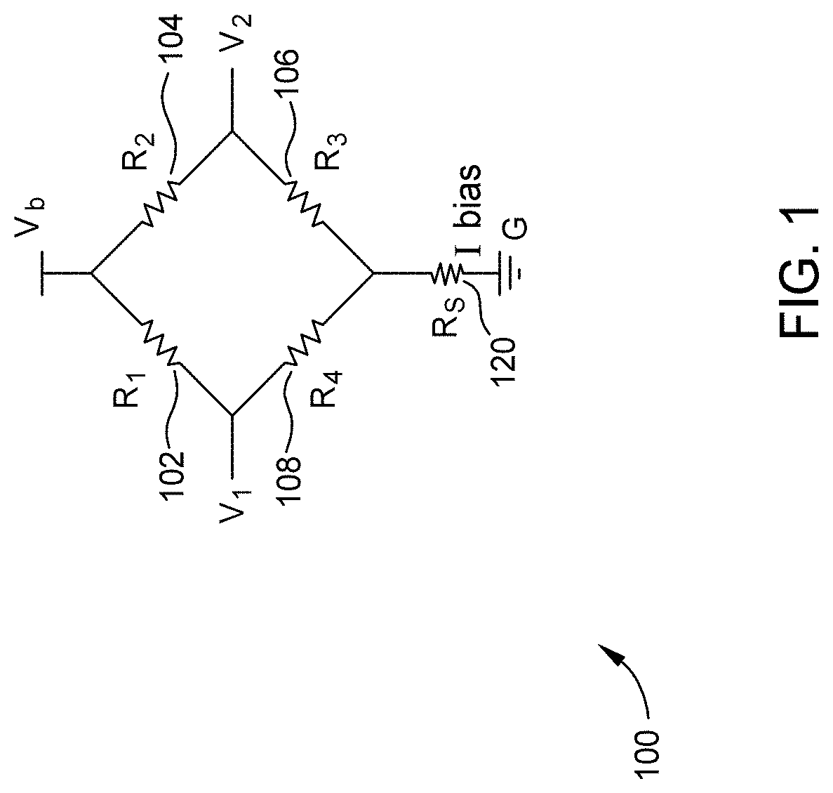
[0063]FIG. 10 shows an output of a Wheatstone sensor bridge using MTJs with a free layer with intrinsic anisotropy of 300 Oe, 600 Oe, or 900 Oe using a simplified uniform rotation model. FIG. 10 shows a high linear response up to the saturation fields equal to the intrinsic anisotropy value.
[0064]In contrast, for MTJ using shape anisotropy alone without intrinsic anisotropy, the sensor response becomes nonlinear at fields well below saturation (70-80%), limiting its useful field range, for the same saturation field.
example 3
[0065]Various ferromagnetic materials were deposited at angle from normal deposition. The intrinsic anisotropies (HK) and the corresponding coercivities for the easy axis (HCE) were measured and set forth in TABLE 1. In examples A, C, G, H, a single film was deposited to the specified thickness by physical vapor deposition at the specified oblique angle from normal utilizing either CIS PVD tool or a LS PVD tool. In examples B, E, F, a bi-layer film was deposited utilizing two different materials to the specified thicknesses by physical vapor deposition at the specified oblique angles from normal. In example E, NiTa was deposited at a 70° from normal and then NiFe19 was deposited at a zero degree from normal (i.e., regular physical vapor deposition with an angle of 0°). In example D, ten layers of 20A thick NiFe19 was deposited for a total thickness of 100 Å. The data shows that sensor can be made with a free layer formed of a material deposited at an angle in which the free layer ha...
PUM
 Abstract
Description
Claims
Application Information
 - R&D Engineer
- R&D Manager
- IP Professional
- Industry Leading Data Capabilities
- Powerful AI technology
- Patent DNA Extraction
Browse by: Latest US Patents, China's latest patents, Technical Efficacy Thesaurus, Application Domain, Technology Topic, Popular Technical Reports.
© 2024 PatSnap. All rights reserved.Legal|Privacy policy|Modern Slavery Act Transparency Statement|Sitemap|About US| Contact US: help@patsnap.com