Devices and methods to form a randomly ordered array of magnetic beads and uses thereof

a randomly ordered array and magnetic particle technology, applied in the field of randomly ordered arrays of magnetic particles, can solve the problems of difficult adaptability or reuse of arrays, high labor intensity and time consumption, and subject to variability

Active Publication Date: 2010-03-23
THE BOARD OF TRUSTEES OF THE LELAND STANFORD JUNIOR UNIV
View PDF28 Cites 46 Cited by
  • Summary
  • Abstract
  • Description
  • Claims
  • Application Information

AI Technical Summary

Problems solved by technology
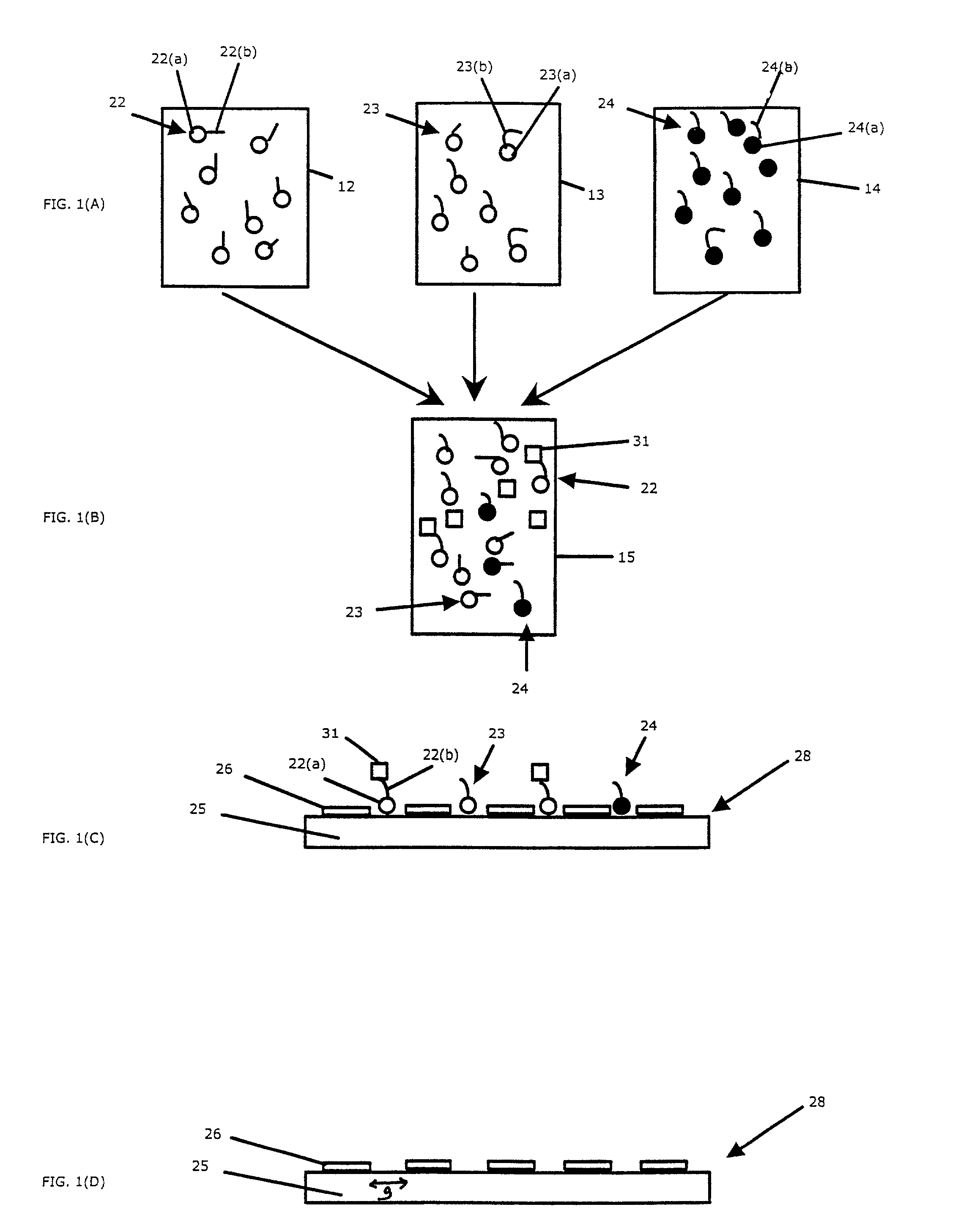
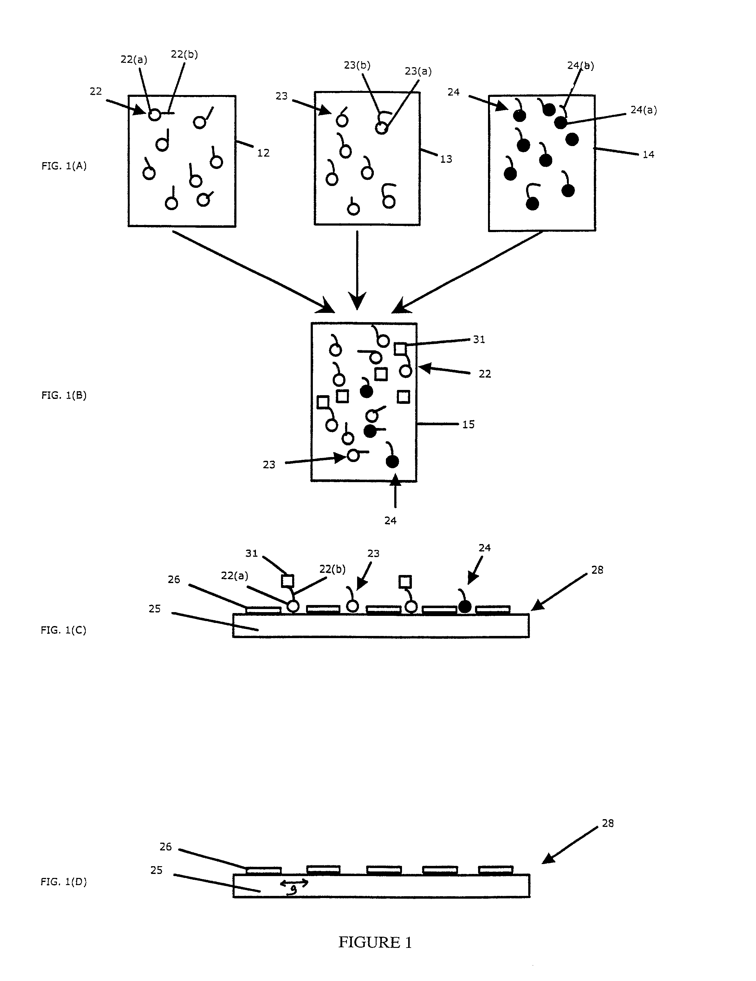
These techniques typically require multiple fabrication steps, are labor-intensive and time-consuming, and are subject to variability.
Such arrays are not easily adaptable or reusable as the probes are permanently bound to the substrate.
In addition, these arrays suffer from a significant lack of flexibility since a new fabrication protocol is needed to change any of the probe sequences or to add new probes to the array.

Method used


Image

  • Devices and methods to form a randomly ordered array of magnetic beads and uses thereof
  • Devices and methods to form a randomly ordered array of magnetic beads and uses thereof
  • Devices and methods to form a randomly ordered array of magnetic beads and uses thereof

Examples


example 1

Fabricating Magnetic Chips

[0165](1) Cobalt film approximately 700-1000 nm thick was deposited on a silicon wafer with a diameter of approximately 3.0 inches. The cobalt layers were sputtered sequentially without breaking vacuum using a UHV DC magnetron sputtering system at 2×10⁻⁸ torr. The deposition rate was 0.39 nm / sec. An e-beam lithographic pattern was written using a Hitachi HL-700F instrument, a direct write patterning tool with a minimum feature size of 50 nm, and a UVN30 photoresist at 5.5 Krpm spin for 40 sec. The resulting photoresist layer was approximately 500 nm thick. The photoresist was then developed with MF-CD 26 for 30 sec. The chip configuration defined by the mask resulted in a pattern of diamond-shaped magnetic regions.

[0166]To fabricate the magnetic islands, argon sputter etching was performed in an ion-milling etcher without breaking vacuum and with the photoresist as the mask. Time intervals of 10 min etching / 10 min cooling were used for a total of 80 min. Th...

example 2

Assembling a Random Array of Magnetic Beads on a Magnetic Chip

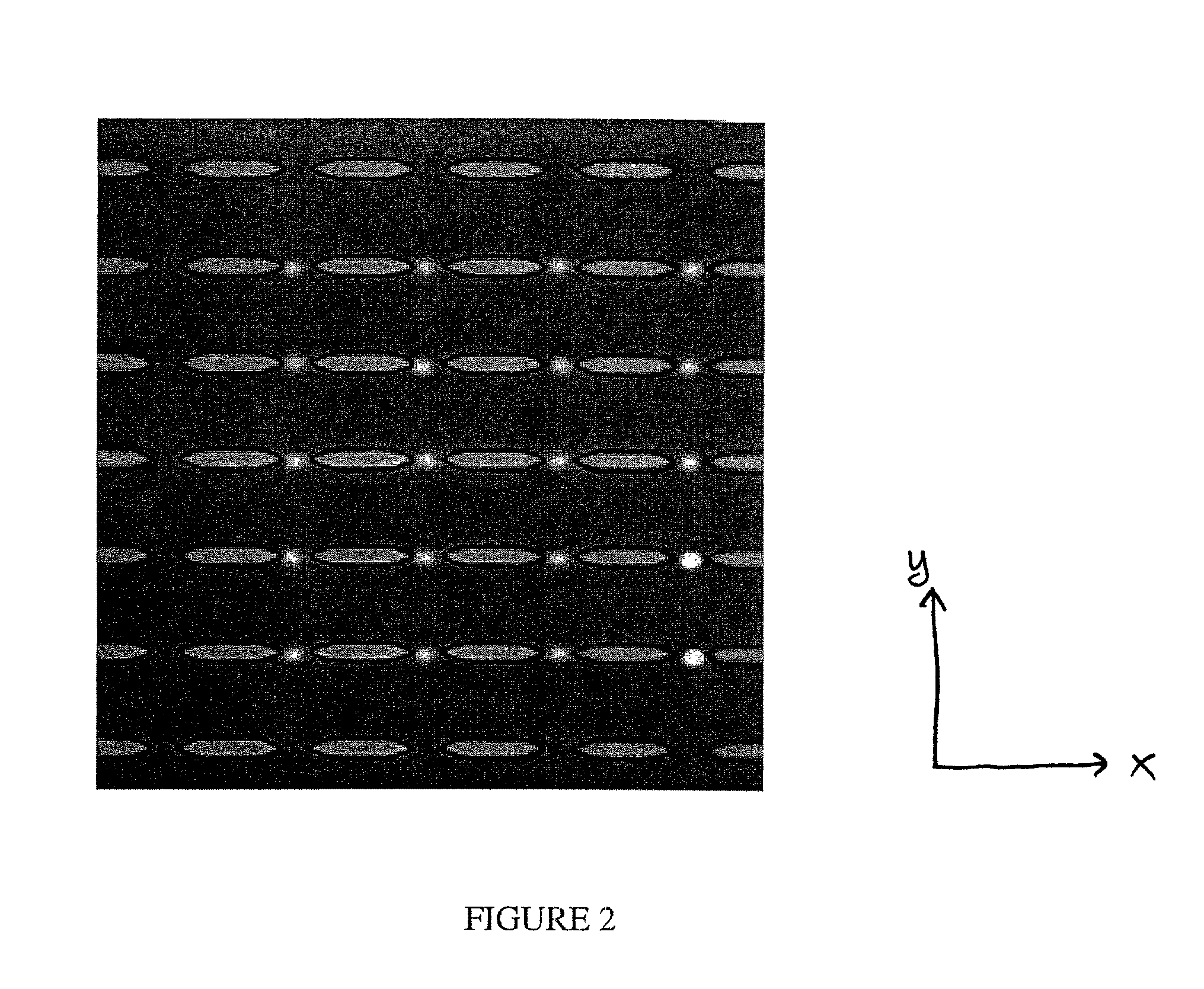
[0168]A magnetic chip was fabricated essentially as described in Example 1 except that (i) the mask was designed to produce a chip with a 10×10 array of arrays, with each subarray having a 30×30 configuration of magnetic islands; (ii) the magnetic islands were diamond-shaped rather than rectangular and had an island-to-island spacing of approximately 20 μm in both the x- and y-dimensions, and (ii) the etching time was varied across the chip in the x-dimension, resulting in a gap of variable width, ranging between 1 and 4 μm.

[0169]A stock solution of superparamagnetic beads (streptavidin-conjugated M-280 Dynabeads obtained from Dynal Biotech, Inc.) was washed with buffer according to the directions of the manufacturer and labeled with biotinylated fluorescent R-phycoerythrin dye (Molecular Probes, Inc.) also according to the directions of the manufacturer. The beads were diluted at 40:1 in 1×TE (Tris-EDTA) with 0.1% SDS, y...

example 3

Detecting DNA Hybridization Using a Random Array of Magnetic Beads

[0172]A stock solution of superparamagnetic streptavidin-conjugated M-280 Dynal beads (10 mg / ml) was cleaned thrice following the manufacturer's directions. The stock beads are specified to bind up to 20 pmole of biotinylated oligo per 10 ul of stock beads. We cleaned 10 ul of stock beads and diluted them 2-fold to 20 ul. 200 pm of biotinylated oligo (2 ul of 100 pm / ul) was then added and bound to the bead for 30 minutes at 40° C. while shaking on an Eppendorf Thermomixer. 1M NaCl salt buffer conditions were used, in accordance to the manufacturer's protocols. A ten fold excess of biotinylated oligo was used to saturate all the available binding sites on the bead. The oligo sequence used was 5′-[BiotinTEG]TTT TTT ACT GGC CGT CGT TTT ACA-3′ The six T's closest to the 5′end were inserted to form a linker for the 18-mer oligo. These may not be necessary.

[0173]The beads were then captured (magnetically) and excess oligo r...


PUM

PropertyMeasurementUnit
sizeaaaaaaaaaa
lengthaaaaaaaaaa
lengthaaaaaaaaaa

Abstract

The invention includes devices and methods for forming random arrays of magnetic particles, arrays formed using these devices and methods, and to methods of using the arrays. The invention provides an assembly (chip) with magnetic domains that produce localized magnetic fields capable of immobilizing magnetic particles such as commercially available magnetic beads. Probe or sensor molecules can be coupled to the beads, which are then dispersed on the assembly, forming a random order array. The arrays can be used for analyzing samples, targets, and / or the interaction between samples and targets. The invention finds particular use in processes such as high-throughput genotyping and other nucleic acid hybridization-based assays.

Description

CROSS REFERENCE TO RELATED APPLICATIONS[0001]This application claims the benefit of U.S. Provisional Application No. 60 / 223,125, filed Aug. 7, 2000, which is incorporated herein by reference in its entirety for all purposes. Inventors' U.S. Provisional Application No. 60 / 202,357, filed May 5, 2000, is also incorporated herein by reference in its entirety.[0002]This invention was made with U.S. Government support pursuant to grant no. HG 00205 from the National Institutes of Health. The U.S. Government may have certain rights in this invention.FIELD OF THE INVENTION[0003]Embodiments of the invention relate to devices and methods for forming arrays of magnetic particles, arrays of such particles, and uses of the arrays.BACKGROUND OF THE INVENTION[0004]Progress in biology and in chemistry is leading to an ever-increasing demand for high-throughput, cost-effective analysis of complex mixtures. This demand has in turn stimulated the development of compact, high-density array devices. The...

Claims


Application Information

Patent Timeline
Patent Type & Authority Patents(United States)
IPC IPC(8): G01N33/551C12Q1/00B03C1/035C12Q1/68G01N35/00
CPCB03C1/035C12Q1/6837B01J2219/00274B01J2219/00542B01J2219/00549B01J2219/00563B01J2219/00655Y10T428/24355G01N2035/00574Y10S428/90G01N35/0098C12Q2563/143C12Q2563/107
Inventor JAIN, MANEESHWHITE, ROBERT L.ROBERTS, LESTER A.
Owner THE BOARD OF TRUSTEES OF THE LELAND STANFORD JUNIOR UNIV
Why Eureka
Try Eureka