
Method and device for producing air product based on cryogenic rectification

a technology of cryogenic rectification and air product, which is applied in the direction of lighting and heating apparatus, refrigeration and liquid storage, solidification, etc., can solve the problems of greatly increasing production cost, achieve greater flexibility, reduce production cost, and increase the oxygen gas extraction rate of the device

Active Publication Date: 2021-03-11
LAIR LIQUIDE SA POUR LETUDE & LEXPLOITATION DES PROCEDES GEORGES CLAUDE
View PDF0 Cites 1 Cited by
  • Summary
  • Abstract
  • Description
  • Claims
  • Application Information

AI Technical Summary

Benefits of technology

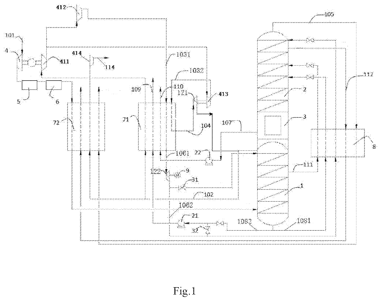
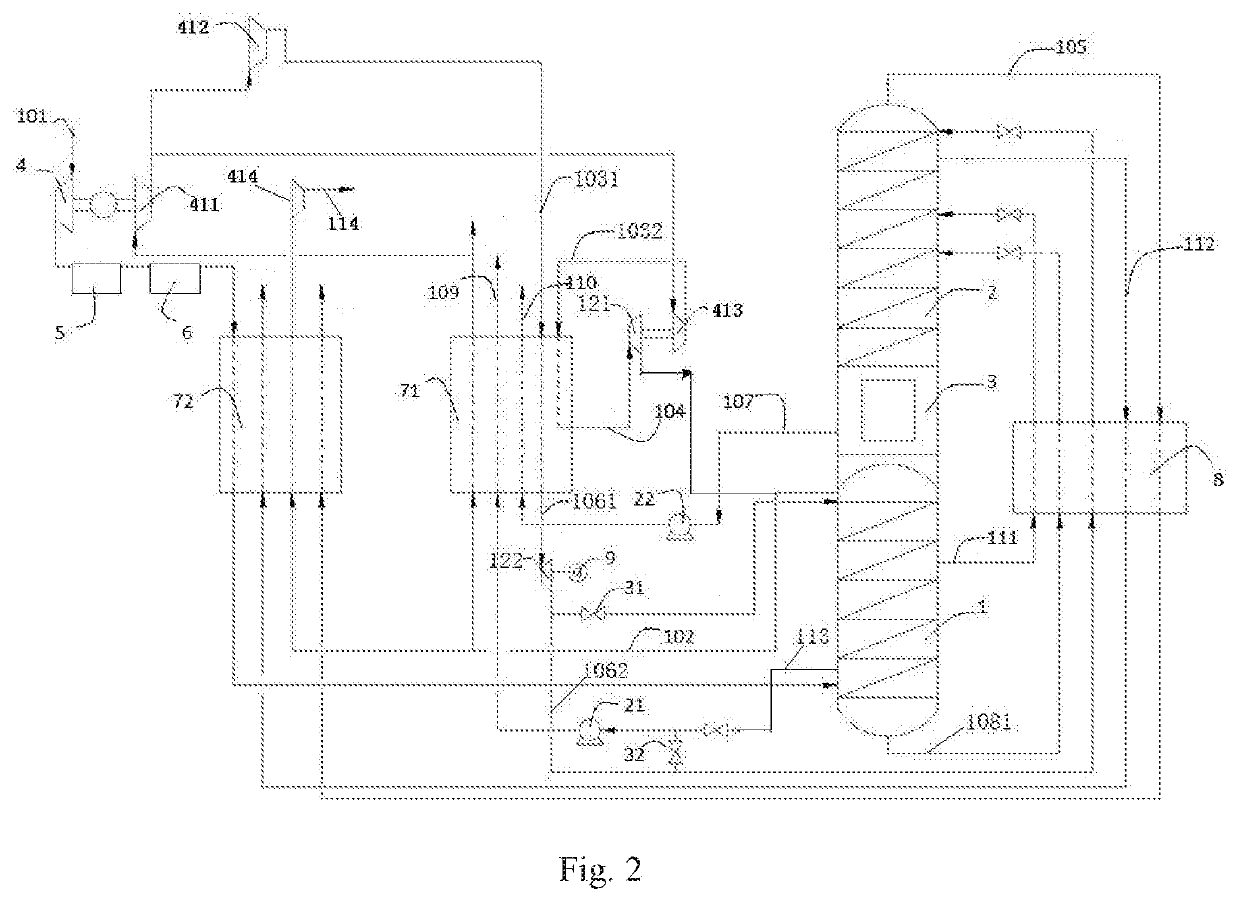
The present invention provides a method and apparatus for producing an air product using cryogenic rectification to reduce production costs and provide flexibility. The method involves using a liquid pump to increase the pressure of oxygen-rich liquid air, which is then vaporized by high-pressure nitrogen gas in the main heat exchanger to obtain the required air product. This method avoids the need for an additional air booster, reducing production costs and allowing for greater flexibility. The apparatus includes a regulator valve to adjust the nitrogen-oxygen ratio in the outputted air product. This method also increases the oxygen gas extraction rate, improving energy efficiency.

Problems solved by technology

However, in a nitrogen gas circulation process, due to the lack of an air booster, if there was a need to produce an air product of medium-to-high pressure then the usual method adopted in the past was to use an independent air booster, thus the production cost was greatly increased.

Method used


Image

  • Method and device for producing air product based on cryogenic rectification
  • Method and device for producing air product based on cryogenic rectification

Examples


Embodiment Construction

[0044]The present invention is described further below in conjunction with the drawings by means of particular embodiments, which are merely intended to explain the present invention without limiting the scope of protection thereof.

[0045]In the present invention, the term “air feed gas” means a mixture containing mainly oxygen and nitrogen.

[0046]The term “impure nitrogen gas” covers gaseous fluids with a nitrogen content generally not lower than 95 mol %; the term “impure liquid nitrogen” means a liquid fluid with a molar percentage of nitrogen generally greater than 95.

[0047]The term “oxygen-rich liquid air” means a liquid fluid with a molar percentage of oxygen greater than 30; the term “liquid air” means a liquid fluid with a molar percentage of oxygen not greater than 30; the term “liquid oxygen” covers liquid fluids with a molar percentage of oxygen greater than 99, and the content of oxygen in “liquid oxygen” is higher than that in “oxygen-rich liquid air”.

[0048]The cryogenic ...


PUM


Abstract

A method and a device for producing an air product based on cryogenic rectification; after being cooled by a main heat exchanger, raw material air and nitrogen compressed by means of a compressor are sent to a rectification system for low temperature separation. In the rectification system, products such as oxygen and nitrogen are obtained by means of low temperature separation, and oxygen-enriched liquid air is obtained at or near the bottom of a rectification tower. The oxygen-enriched liquid air or liquid-state air in the rectification system is sent out after being raised to a target pressure by means of a low temperature liquid air pump; air products of various pressures can be produced by means of selecting low temperature liquid air pumps with different lifts or by connecting in series different amounts of low temperature liquid air pumps. The present method can avoid the need to arrange additional air compressors, entirely changing the method for producing medium and high pressure air products in a nitrogen circulation process, and importantly can reduce production costs significantly whilst having greater flexibility. In addition, the present method can increase the oxygen extraction rate of an apparatus, thereby improving the energy efficiency level.

Description

TECHNICAL FIELD[0001]The present invention relates to the field of cryogenic air separation, in particular to a method and apparatus for producing an air product on the basis of cryogenic rectification.BACKGROUND ART[0002]Cryogenic separation, also known as cryogenic rectification, was invented in 1902 by Professor Linde. It is essentially a gas liquefaction technique. Generally using a mechanical method such as throttling expansion or adiabatic expansion, gases are compressed and cooled, then the differences in boiling points of different gases are used to perform rectification, such that the different gases are separated.[0003]The principle of cryogenic air separation is to take air as a starting material, and after compression and purification, heat exchange is used to liquefy the air to liquid air. Liquid air is mainly a mixture of liquid oxygen and liquid nitrogen; using the difference in boiling points of liquid oxygen and liquid nitrogen, they are separated by rectification t...

Claims


Application Information

Patent Timeline
IPC IPC(8): F25J3/04
CPCF25J3/04018F25J3/0403F25J3/04412F25J3/04357F25J3/0409F25J3/04145F25J3/04224F25J3/04387F25J2240/12F25J2245/42F25J2215/40F25J2215/02F25J3/04078
Inventor ZHAO, BOWEIBRIGLIA, ALAINXUE, FENGJIE
Owner LAIR LIQUIDE SA POUR LETUDE & LEXPLOITATION DES PROCEDES GEORGES CLAUDE
Learn More