Redox flow battery and method of operation
a technology flow outlet, which is applied in the field can solve the problems of large footprint of existing large volume of storage tank required to store electrolyte, etc., and achieve the effect of reducing the footprint reducing the lifetime of redox flow battery system, and simple effective management of fluid flow through the system
- Summary
- Abstract
- Description
- Claims
- Application Information
AI Technical Summary
Benefits of technology
Problems solved by technology
Method used
Image

Examples
example 1
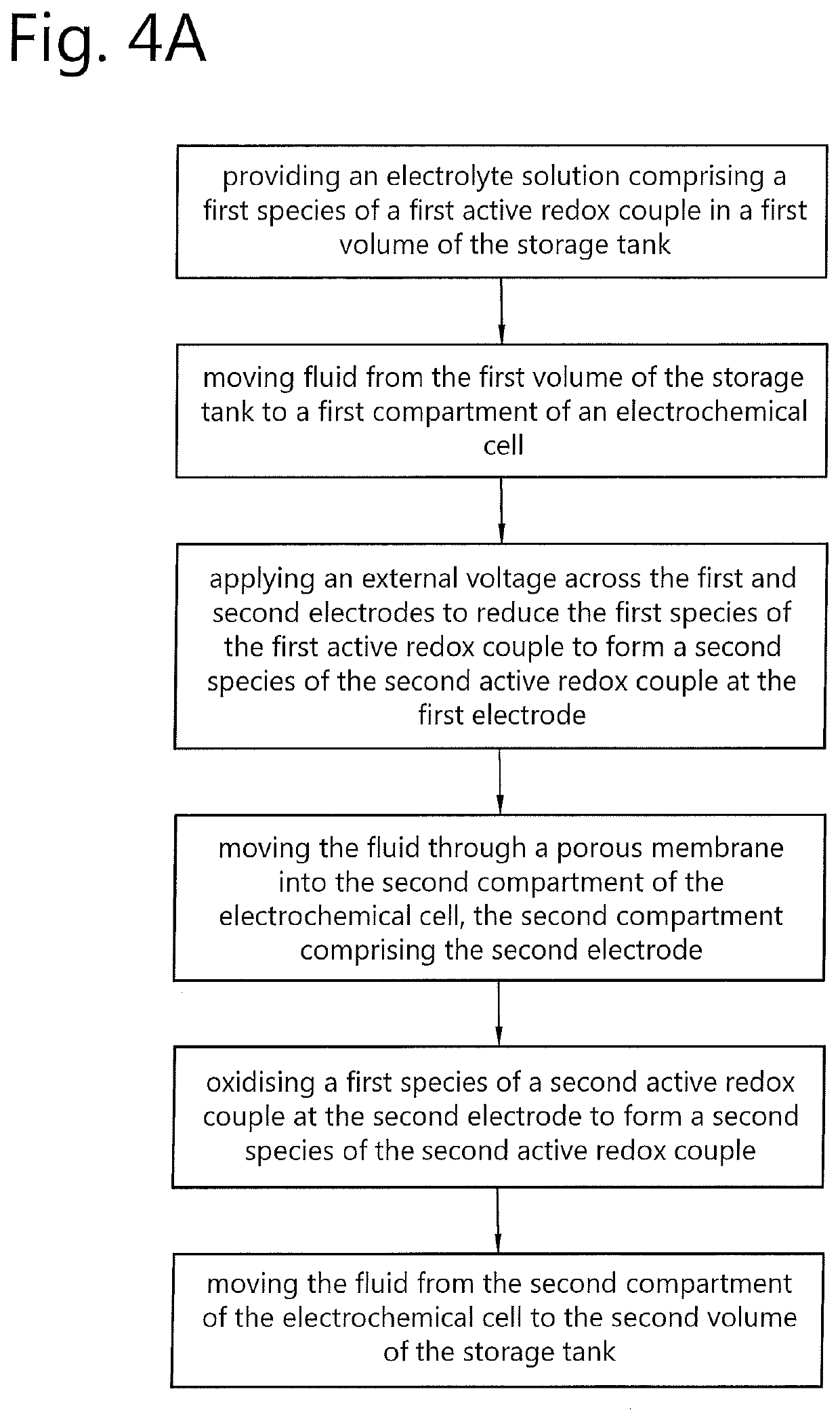
[0069]
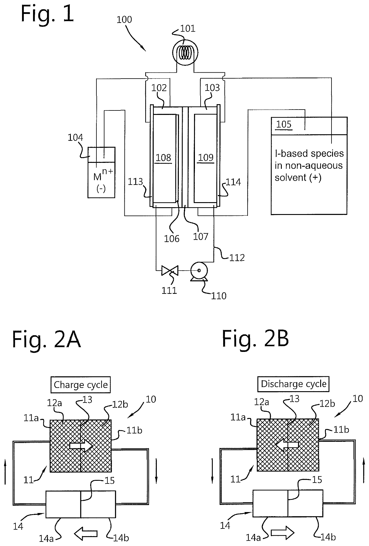
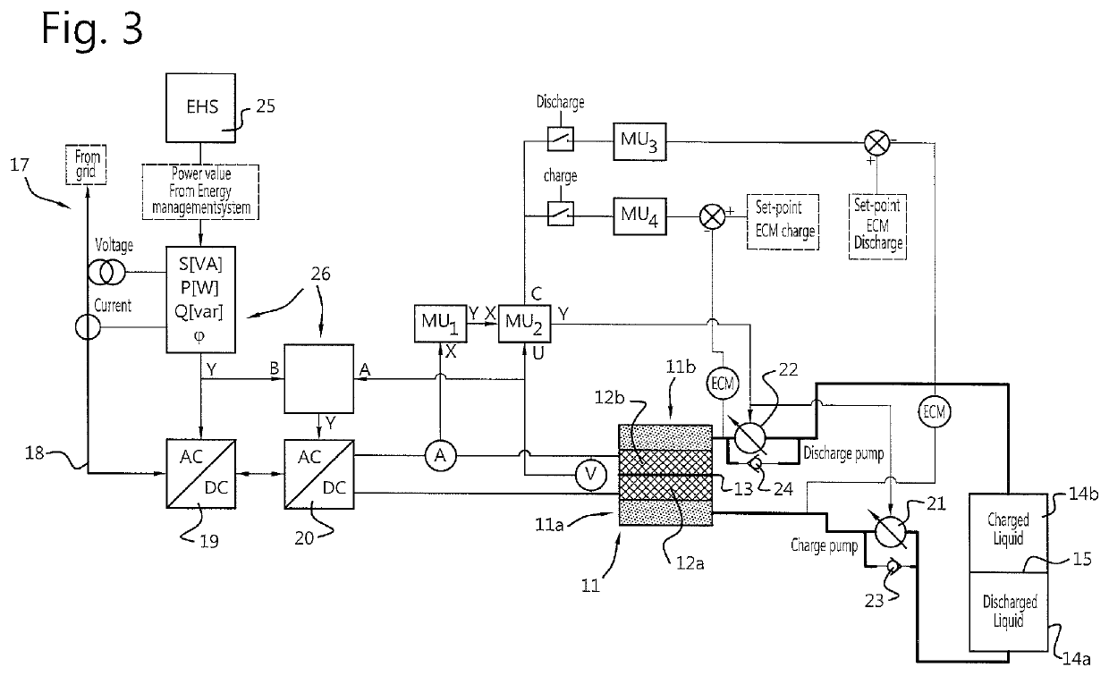
Charge cycleDischarge cycleFirst volume of3ZnI2Second volume ofZnI6storage tankstorage tankAt first electrode3Zn2+ + 4e−→ 2Zn0 + Zn2+At second2I2 + 2I− + 4e−→ 6I−electrodeMoves acrossZn2+ + 6I−Moves acrossZn2+ + 6I−membranemembraneAt second6I−− 4e−→ 2I2 + 2I−At first electrode2Zn0 + Zn2+− 4e−→ 3Zn2+electrodeSecond volume ofZnI6First volume of3ZnI2storage tankstorage tank[0070]Electrodes: Porous carbon electrodes e.g. carbon felts[0071]Voltage: Charging >1.3 V; discharge at 1.3 V[0072]Solvent: Water, e.g. containing additives for preventing dendrite formation of the Zn0 [0073]Membrane: Porous non-charged membrane (configured to allow passage of I− and Zn2+ through the membrane)
example 2
[0074]
Charge cycleDischarge cycleFirst volume ofZnI2Second volume ofH2Ostorage tankstorage tankAt first electrodeZn2+ + 2e−→At secondI2 + 2e−→ 2I−Zn0electrodeMoves across2I−Moves across2I−membranemembraneAt second2I−− 2e−→ I2At first electrodeZn0 − 2e−→ Zn2+electrodeSecond volume ofH2OFirst volume of2ZnI2storage tankstorage tank[0075]Electrodes: Porous carbon electrodes e.g. carbon felts[0076]Voltage: Charge >1.3 V; discharge at 1.3 V[0077]Solvent: Water, e.g. containing additives for preventing dendrite formation of the Zn0 [0078]Membrane: Porous membrane, preferably a positively charged porous membrane (configured to allow passage of I− but substantially prevent or limit passage of Zn2+ therethrough)
example 3
[0079]
Charge cycleDischarge cycleFirst volume ofZnCl2 + 2FeCl2Second volume of2FeCl3storage tankstorage tankAt first electrodeZn2+ + 2e−→At second2Fe3+ + 2e−→Zn0electrode2Fe2+Moves across6Cl− + 2Fe2+Moves across6Cl− + 2Fe2+membranemembraneAt second2Fe2+− 2e−→At first electrode Zn0 − 2e−→electrode2Fe3+Zn2+Second volume of2FeCl3First volume ofZnCl2 + 2FeCl2storage tankstorage tank[0080]Electrodes: Porous carbon electrodes e.g. carbon felts[0081]Voltage: Charge >1.53 V; discharge at 1.53 V[0082]Solvent: Water, e.g. slightly acidic (e.g. HCl) and preferably containing additives for preventing dendrite formation of the Zn0 [0083]Membrane: Porous non-charged membrane (configured to allow Fe2+ also Cl− to pass therethrough)
PUM
| Property | Measurement | Unit |
|---|---|---|
| volume | aaaaa | aaaaa |
| volumes | aaaaa | aaaaa |
| conductivity | aaaaa | aaaaa |
Abstract
Description
Claims
Application Information
 - R&D
- Intellectual Property
- Life Sciences
- Materials
- Tech Scout
- Unparalleled Data Quality
- Higher Quality Content
- 60% Fewer Hallucinations
Browse by: Latest US Patents, China's latest patents, Technical Efficacy Thesaurus, Application Domain, Technology Topic, Popular Technical Reports.
© 2025 PatSnap. All rights reserved.Legal|Privacy policy|Modern Slavery Act Transparency Statement|Sitemap|About US| Contact US: help@patsnap.com