
Rectification device having standby power reduction function

a technology of rectification device and function, which is applied in the direction of dc-dc conversion, power conversion system, instruments, etc., can solve the problems reduced lifespan of high voltage capacitor used for smoothing dc, and addition of high voltage power stress to circuit components. , to achieve the effect of reducing standby power, preventing surge voltage, and low power consumption

Active Publication Date: 2021-03-11
JEONG YEON MOON
View PDF0 Cites 0 Cited by
  • Summary
  • Abstract
  • Description
  • Claims
  • Application Information

AI Technical Summary

Benefits of technology

The present invention provides a technology that stabilizes DC power without using an electrolytic capacitor in a power supply system. It does this by using a resistance value to control the current flow through a capacitor and discharging the capacitor when the voltage becomes too smooth. This invention also allows for low-power data transmission and insulation from external devices, as well as reducing standby power.

Problems solved by technology

In addition, a high voltage capacitor used for smoothing the DC has a reduced lifespan due to stress caused by the AC power, and the power factor thereof is not good because smoothing is performed by a simple method in which an AC voltage is rectified through a rectifier, and then, the rectified voltage is charged by the capacitor.
Accordingly, there occurs an issue in that a high voltage power stress is added to a circuit component and the SMPS does not continuously supply a stable DC power.
In addition, since the SMPS uses a large electrolytic capacitor in the internal circuit, the size of the DC conversion device also becomes large.

Method used


Image

  • Rectification device having standby power reduction function
  • Rectification device having standby power reduction function
  • Rectification device having standby power reduction function

Examples


Embodiment Construction

[0033]Hereinafter, it will be described in detail about an exemplary embodiment of the present invention in conjunction with the accompanying drawings.

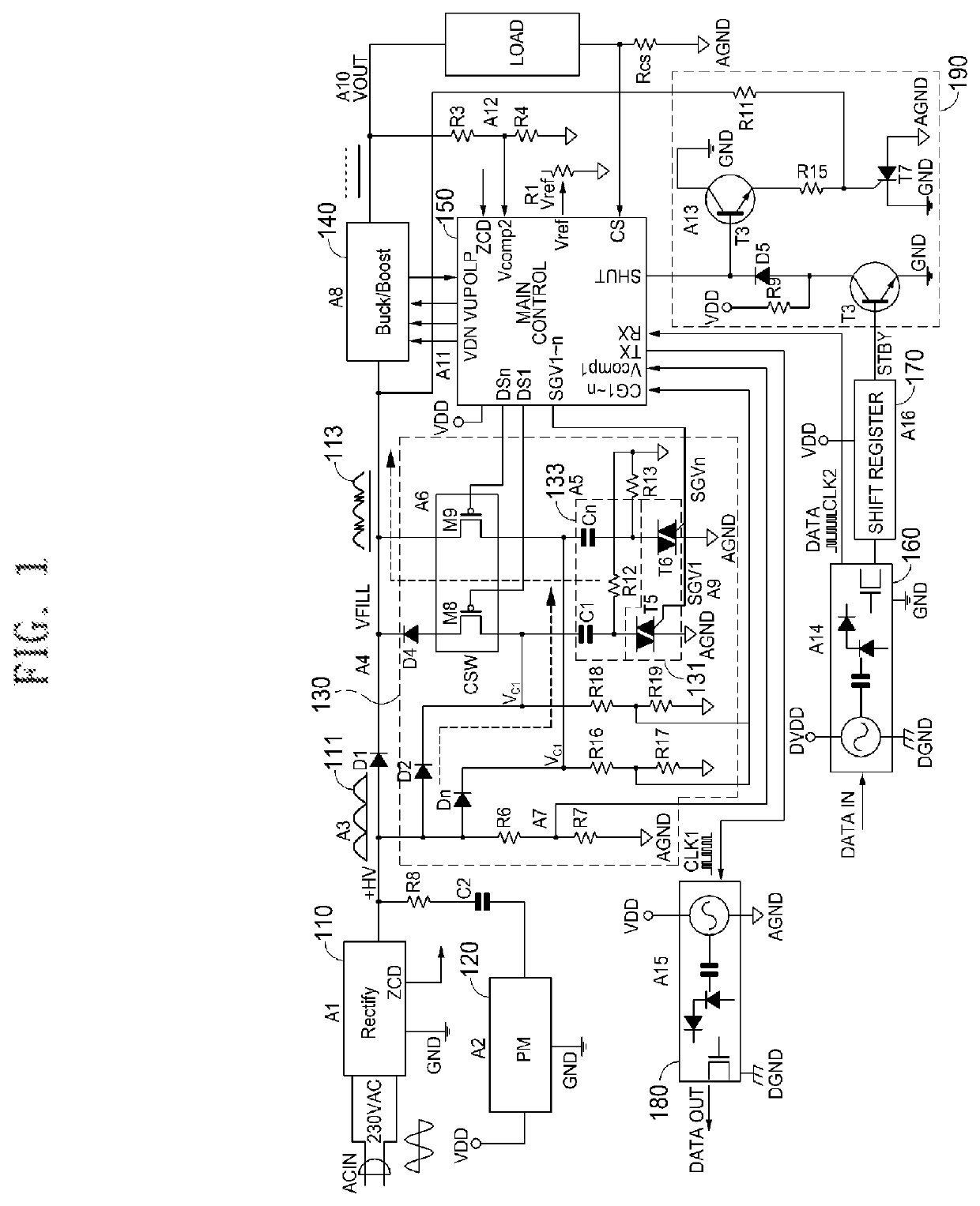
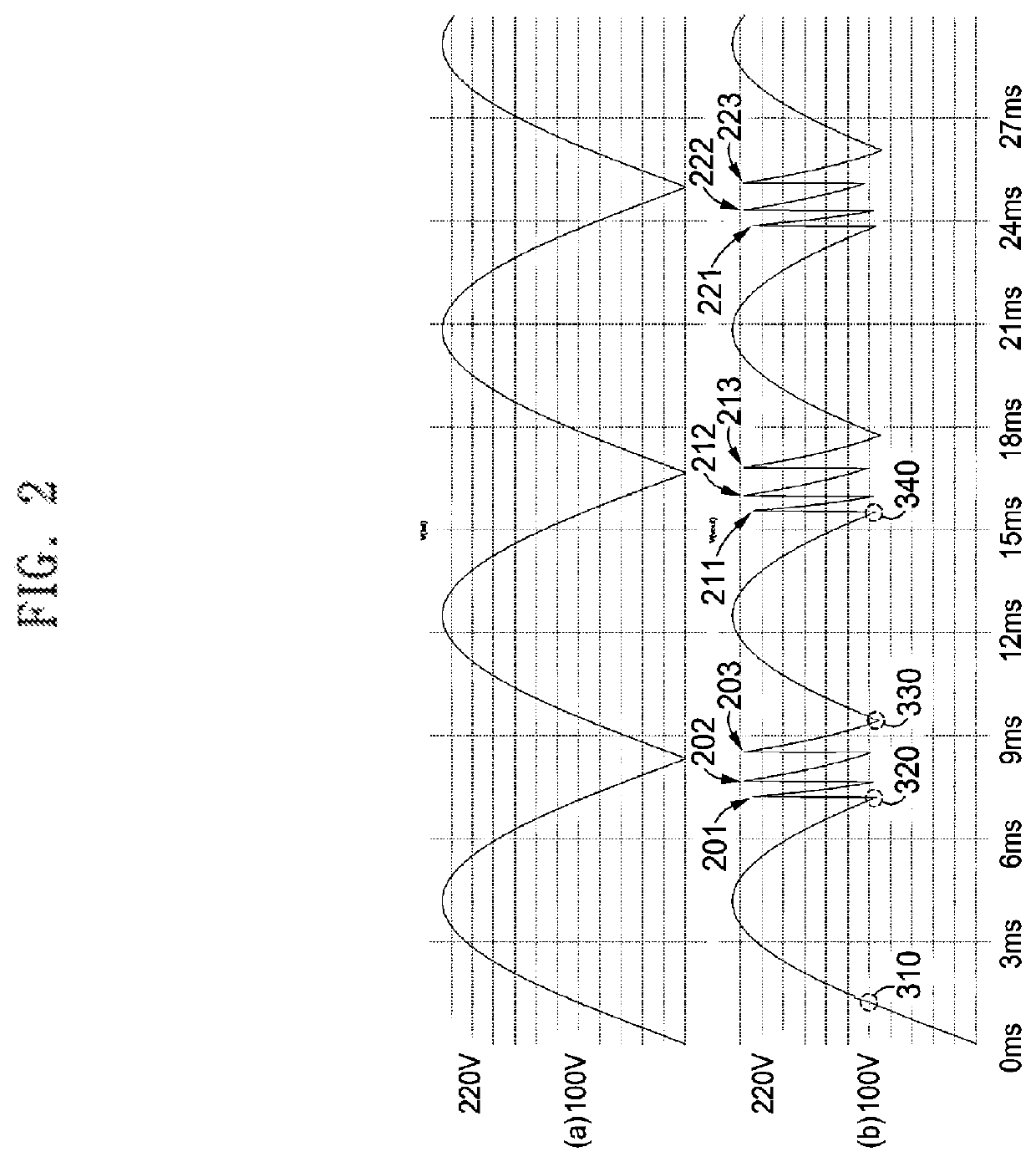
[0034]FIG. 1 is a circuit diagram illustrating the entire configuration of a rectifying device provided with a standby power reduction function according to a preferred embodiment of the present invention, and FIG. 2 illustrates a DC smoothing scheme according to a preferred embodiment of the present invention.

[0035]With reference to FIGS. 1 and 2, a rectifying device provided with a standby power reduction function includes a rectifying unit (Rectify) 110, a power management unit (PM) 120, a charging and discharging unit 130, a main control unit (MAIN CONTROL) 150, a buck / boost circuit unit (Buck / Boost) 140, a data receiving unit 160, a data transmission unit 180, a shift register 170, and an operation switching unit 190.

[0036]The rectifying unit 110 receives AC power from the commercial power source, rectifies the AC power to DC pow...


PUM


Abstract

Disclosed is a rectifying device provided with a standby power reduction function. When a voltage of unsmoothed DC power, which is output from a rectifying unit that rectifies AC power, is lowered to be equal to or smaller than a discharge reference voltage at a time around a zero-crossing point of the AC power, the present invention can instantaneously discharge a capacitor, which has been charged with the unsmoothed DC power, to be synthesized with the unsmoothed DC power, and thus supply stable DC power to a load without using an electrolytic capacitor. In particular, the present invention can adjust a resistance value of a surge prevention switch connected in series with the capacitor to control a current amount flowing through the capacitor, and thus can prevent a surge voltage from being generated when charging and discharging the capacitor.

Description

TECHNICAL FIELD[0001]The present invention relates to a rectifying device, and more particularly, to a rectifying device having a standby power reduction function and converting AC power into DC power.BACKGROUND ART[0002]Since a voltage value of AC power supplied from a commercial power source is not constant, DC power can be stably used by smoothing AC to DC using a high voltage capacitor or the like in a procedure in which the AC power is converted to be used as the DC power.[0003]In addition, a high voltage capacitor used for smoothing the DC has a reduced lifespan due to stress caused by the AC power, and the power factor thereof is not good because smoothing is performed by a simple method in which an AC voltage is rectified through a rectifier, and then, the rectified voltage is charged by the capacitor.[0004]In particular, an aluminum electrolytic capacitor typically used for smoothing a high DC voltage has a large size and large internal resistance, and the inside thereof is...

Claims


Application Information

Patent Timeline
Patent Type & Authority Applications(United States)
IPC IPC(8): H02M3/158H02M7/217
CPCH02M3/1582H02M7/217H02M1/14H02M7/155H02M3/158H02M1/007
Inventor JEONG, YEON MOON
Owner JEONG YEON MOON
Learn More