
A method and system for layerwise forming an object from a medium capable of solidification

a technology of solidification medium and layerwise forming, which is applied in the direction of applying layer means, manufacturing tools, inking apparatus, etc., can solve the problems of inaccurate layer deposition, significant amount of resin may not pass the recoater or be dragged, and inability to pass the recoater or other problems, to prevent eventual dripping and/or wetting, and improve the effect of forming accuracy

Pending Publication Date: 2021-03-18
NEDERLANDSE ORG VOOR TOEGEPAST-NATUURWETENSCHAPPELIJK ONDERZOEK (TNO)
View PDF3 Cites 1 Cited by
  • Summary
  • Abstract
  • Description
  • Claims
  • Application Information

AI Technical Summary

Benefits of technology

The invention is about a way to deposit layers of material accurately and smoothly, without causing any problems or unevenness in the deposition. This method and system can even allow for faster speeds of movement in the coating process. Overall, this invention makes it possible to get a continuous, high-quality coating even at high speeds.

Problems solved by technology

Known recoater methods can result in an inaccurate or time consuming layer deposition while the geometry is in direct contact with the resin.
As a result of the contact, a significant amount of resin may not be able to pass the recoater or may be dragged by the recoater itself.
While vat / bath height may vary during a build job as of the presence of the built object, the amount of dragged resin is typically not well known or controlled, which finally results in an inaccurate layer deposition.
In this way, waves or non-uniformities may be formed over the path, so that a precise deposition is no longer possible.
However, it is challenging for scaling up a curtain or screen to a larger width (e.g. more than 1 meter).
Furthermore, by movement of the coater, air may impinge on the screen, resulting in flow instabilities such as extreme curvatures or even breakage of the screen or curtain, resulting in additional non-uniformities of an applied (successive) layer of resin.
A slit gap can deform as a result of high pressures, which can result in an inaccurate screen thickness.
Additionally, creating a slit with a relatively small gap thickness (e.g. approximately 100 micrometer or smaller) of over a longer length (e.g. approximately 1 meter or larger), combined with a strict gap tolerance (e.g. in the order of micrometers), can be extremely costly and difficult to achieve.

Method used


Image

  • A method and system for layerwise forming an object from a medium capable of solidification
  • A method and system for layerwise forming an object from a medium capable of solidification
  • A method and system for layerwise forming an object from a medium capable of solidification

Examples


Embodiment Construction

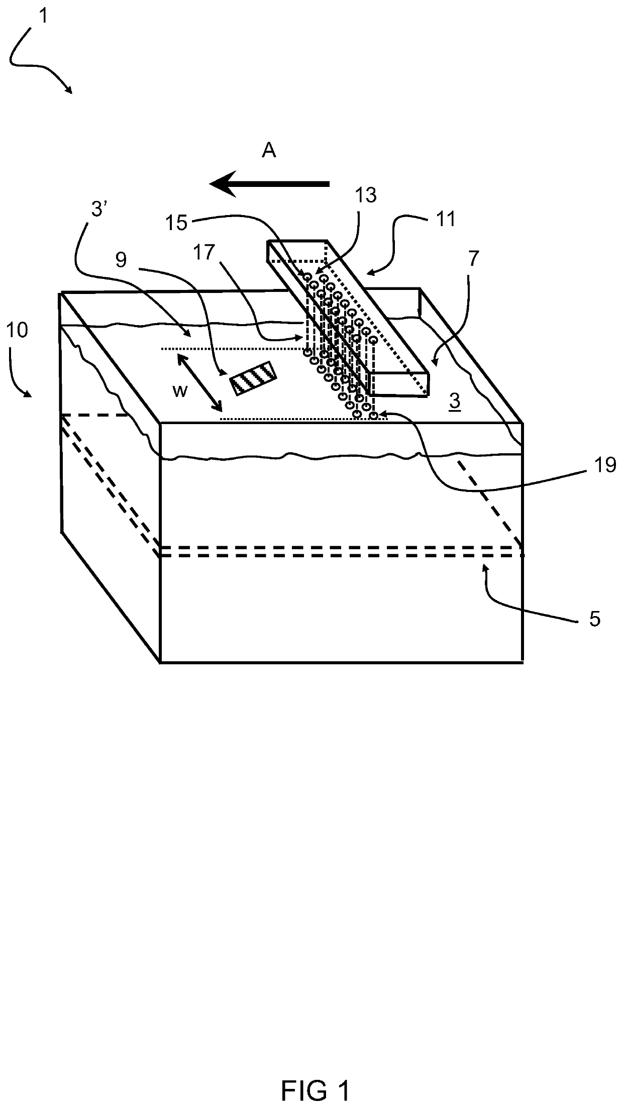
[0125]FIG. 1 shows a perspective view of a schematic diagram of an embodiment of a system 1 configured for layerwise forming an object from a medium 3 capable of solidification. The object is built up layer per layer by repeatedly providing a layer of the medium 3 on a support 5 and / or an already formed part 9 of the object and by subsequently solidifying one or more predetermined areas of the layer of the medium 3 according to a specific pattern before a successive layer 7 is formed in a same manner. The successive layers 7 of the medium 3 are applied using a nozzle head 11 including a plurality of nozzles 13 being spaced apart from each other. Each nozzle has an opening area 15 through which, during application of the successive layer 7, a continuous stream 17 of the medium 3 is discharged for impinging a coverage area 19 on the layer of the medium on the support 5 and / or the already formed part 9 of the object. The plurality of nozzles 13 are arranged to provide non-intersecting ...


PUM

PropertyMeasurementUnit
widthaaaaaaaaaa
hydraulic pressuresaaaaaaaaaa
lengthaaaaaaaaaa

Abstract

An additive manufacturing method and system for layerwise forming an object from a medium capable of solidification, wherein successive layers of the medium are applied using a nozzle head including a plurality of discrete nozzles being spaced apart from each other, each nozzle having an opening area through which a continuous stream of the medium is dischargeable for impinging a coverage area on a layer of the medium on a support and / or an already formed part of the object. The continuous streams are non-intersecting. The nozzle head and the support are relatively movable with respect to each other in at least one running direction.

Description

FIELD OF THE INVENTION[0001]The invention relates to a method and system for layerwise forming an object from a medium capable of solidification. Furthermore, the invention relates to a coater for applying a layer of medium in an additive manufacturing system.BACKGROUND TO THE INVENTION[0002]In the field of additive manufacturing there are a variety of ways in which to create an object. In stereolithography (SLA), complex three-dimensional solid objects can be made by repeatedly laying down thin layers of ultraviolet curable material one layer at a time through the use of (re-)coating means and subsequently selectively solidifying portions of the applied thin layers. The objects can be made quickly without (complex) tooling. A computer can be employed for generating the cross section of patterns. The SLA system can be readily linked to CAD / CAM systems.[0003]Recoating is used in stereolithography for applying a thin layer of medium for a 3D printing application. Typically, the medium...

Claims


Application Information

Patent Timeline
Patent Type & Authority Applications(United States)
IPC IPC(8): B29C64/124B29C64/209B33Y30/00B33Y10/00
CPCB29C64/124B33Y10/00B33Y30/00B29C64/209B41J2/02B41J2202/21
Inventor OLIESLAGERS, RUUDSMELTINK, JEROEN ANTHONIUSVAN HERP, JEROEN ARJAN
Owner NEDERLANDSE ORG VOOR TOEGEPAST-NATUURWETENSCHAPPELIJK ONDERZOEK (TNO)
Features
  • Generate Ideas
  • Intellectual Property
  • Life Sciences
  • Materials
  • Tech Scout
  • Unparalleled Data Quality
  • Higher Quality Content
  • 60% Fewer Hallucinations
Learn More