Electric Servo Dump Gate System On A Crop Duster

a technology of electric servos and crop dusters, which is applied in the direction of gearing, mechanical control devices, instruments, etc., can solve the problems of large amount of equipment and man hours, fatigue or injury, and inability to tie, so as to reduce the number of parts and reduce the number of changes. , the effect of improving the power density

a technology of electric servos and crop dusters, which is applied in the direction of gearing, mechanical control devices, instruments, etc., can solve the problems of large amount of equipment and man hours, fatigue or injury, and inability to tie, so as to reduce the number of parts and reduce the number of changes. , the effect of improving the power density

US20210107630A1Active Publication Date: 2021-04-15REABE TROY

Image

  • Electric Servo Dump Gate System On A Crop Duster
  • Electric Servo Dump Gate System On A Crop Duster

Examples


Embodiment Construction

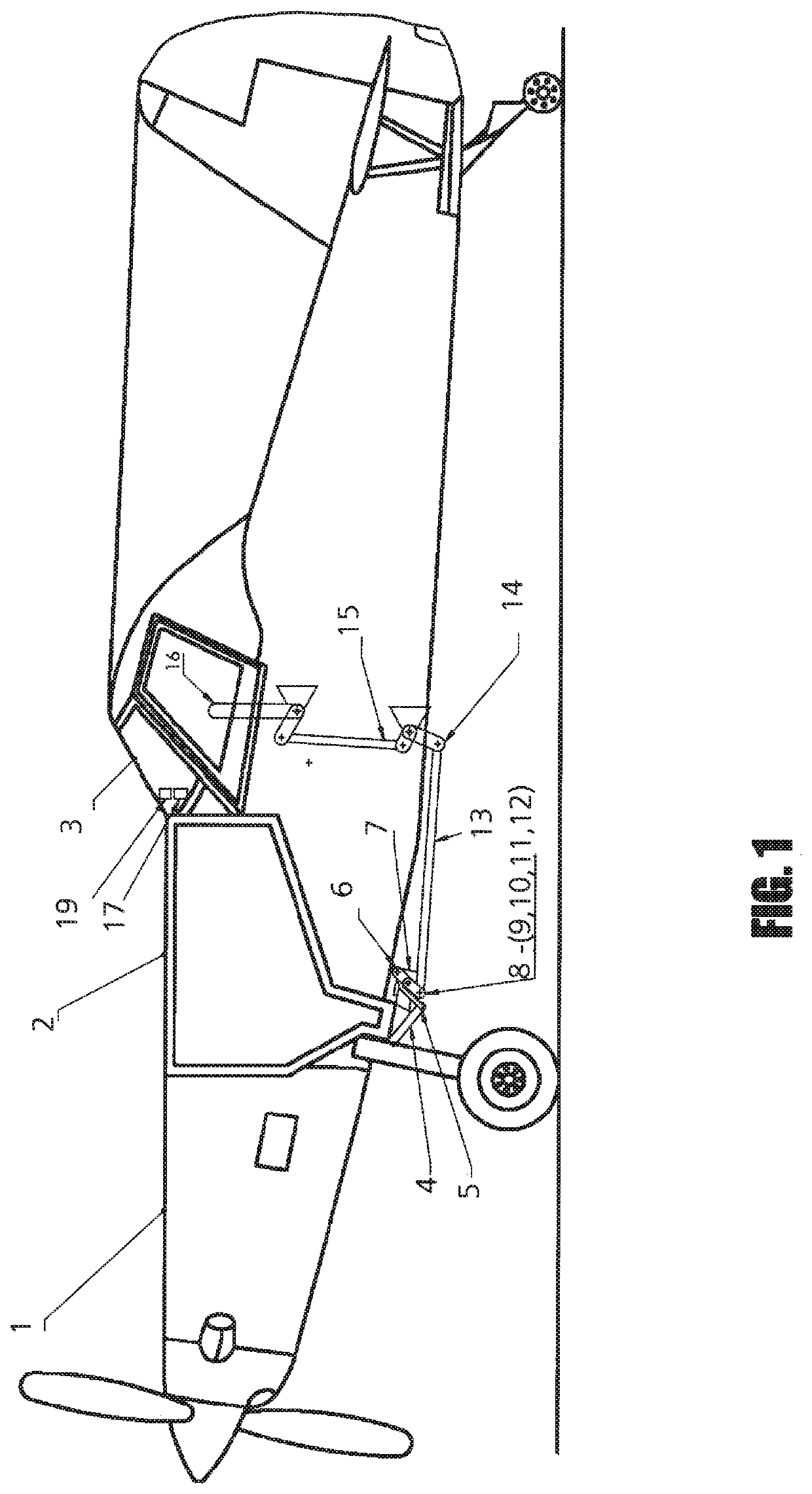
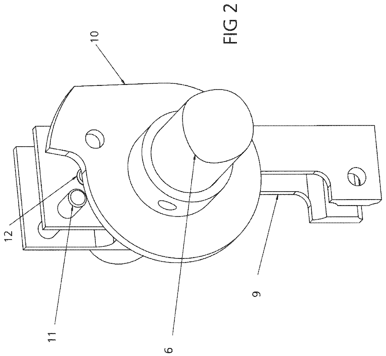
[0027]As stated above, a crop duster dump gate opens and closes to turn on and off the flow of payload out of the hopper. The Electric servo system is actuated by the pilot through a gate controller, or the gate controller can be bypassed, and the gate can be manually actuated. When the pilot is using the gate controller he can have the controller linked to a GPS system and have the gate automatically adjust for changes in ground speed or application rate changes. If the electric servo fails and stops functioning, the pilot can re-connect the Mechanical gate linkages with the lever, which allows the pilot to actuate the gate and continue work. The electric servo is over-powered and back-driven, or there would be a clutch to disengage; so the gate can be actuated manually. The pilot will lose the added features provided by the GPS, but the mechanical gate control remains.

[0028]The claimed invention differs from what currently exists. The current Mechanical gate has great reliability ...


PUM


Abstract

The present invention is an Electric servo system which controls and automates gate openings based on GPS speed and position data that results in precise and reliable modern variable and constant rate application. The Electric servo system also allows for Mechanical gate linkages to remain intact, resulting in few changes to the aircraft and redundancy of emergency components. A Mechanical input connect / disconnect is used to effortlessly transfer between the automated Electric servo system and the Mechanical gate system.

Description

CROSS REFERENCE TO RELATED APPLICATIONS[0001]This patent application claims the priority to U.S. Provisional Application No. 62 / 743,383, filed on Oct. 9, 2018, the disclosure of which is incorporated herein by reference in its entirety.BACKGROUND OF THE INVENTIONField of the Invention[0002]The present invention relates generally to a crop duster dump gate system, and more particularly to an electric servo dump gate system on a crop duster.Description of Related Art[0003]A crop duster dump gate opens and closes to turn on and off the flow of payload out of the hopper. The traditional Mechanical gate, standard equipment on all crop dusters, is actuated by the pilot through mechanical linkages. The effort required by the pilot to open and close the gate requires significant force that can lead to fatigue or injury. This is a reliable but feature deprived system. The pilot must constantly manually adjust for ground speed variation or accept the undesired variations of application rate a...

Claims


Application Information

Patent Timeline
15 Apr 2021
Publication
US20210107630A1
IPC
B64C19/02; B64D1/16; F16H51/00; G05G1/04; G05G5/00; F16H21/06; F16H21/44
CPC
B64C19/02; B64D1/16; F16H51/00; G05G2505/00; G05G5/005; F16H21/06; F16H21/44; G05G1/04
Inventors
REABE, TROY