Free Fall Simulator Cooling System

a simulator and cooling system technology, applied in the field of free fall simulators, can solve the problems of simulator users' faces, significant discomfort, simulator users' discomfort, etc., and achieve the effects of improving the quality of the air stream, improving the speed profile, and reducing the amount of heat being led away

Active Publication Date: 2021-04-22
STROJIRNA LITVINOV SPOL
View PDF0 Cites 0 Cited by
  • Summary
  • Abstract
  • Description
  • Claims
  • Application Information

AI Technical Summary

Benefits of technology

[0013]With the structure of the new simulator and cooling system as defined above, the following advantageous effects have been observed. Firstly, all of the condensate is captured in the cooling area, thus preventing the carrying away of the condensate droplets into the flight chamber and preventing their contact with users. Specifically, in the above defined configuration, most of the condensate is captured in the pressure chamber. Secondly, more efficient mixing of the cooled air with the rest of the circulating air of the wind tunnel system is achieved. The cooling area formed by the closed pressure chamber captures the cooled air immediately after the air leaves the heat exchanger. Thanks to the presence of the above defined pressure chamber the cooled air is not released into the wind tunnel system in a concentrated stream, but rather more evenly, since the cooled air from the cooling area leaves through the outlet window, which ensures an evenly distributed expulsion of the cooled air. The above described system ensures better mixing of the cooled air and thus prevents the cooled air from getting into contact with users in the flight chamber. Furthermore, the pressure chamber is also suited for better shielding from the noise generated by the cooling system, e.g. by means of a special anti-noise coating of the walls of the pressure chamber. Another advantage of the above defined pressure chamber is the delimitation of a clearly defined area for carrying out maintenance, as well as easier access to the entire cooling system. This can reduce the risk of unexpected simulator down times due to necessary regular maintenance work, which can be done significantly quicker.
[0014]Another advantage is the above defined cooling system evens out and the overall improves quality of the speed profile, thereby also improving air stream quality in the flight chamber, since the expelled air revives the border layer at the walls of the wind tunnel system.
[0015]Heat that created in free fall simulators is usually exhausted into the surrounding environment, without any further use, and the amount of heat being led away is significant. For this reason, it is further disclosed in the context of present invention connecting the waste heat to suitable recuperation heat systems that are part of the building the free fall simulator is installed in, whereby enabling to save otherwise lost heat for useful purposes. Reusing waste heat by means of recuperation is impossible in open cooling systems, where the warm air from the wind tunnel system is released directly to the surrounding atmosphere.
[0016]Other advantageous embodiments of the present invention include one or more of the below listed advantageous technical features:
[0017]the free fall simulator is adapted such that the air cooled in the heat exchanger leaves the heat exchanger in the direction towards inside of the cooling area, and only then the cooled air return back from the cooling area into the wind tunnel system; an advantage of this embodiment lies in fact the it enables better mixing of the hot and cool air; moreover, the configuration of this embodiment also contributes to escaping of the condensate into the flight chamber, instead the condensate is trapped the inside the cooling area;
[0018]the closed pressure chamber comprises at least one intake window and at least one outlet window arranged such that the intake duct is located inside the intake window, and such that the cooled air leaves the cooling area through the outlet window;

Problems solved by technology

First, due to the sudden contact of the hot air with the cooling medium, the development of small water condensate droplets has been observed, these droplets are carried away by the air stream and get through into the flight chamber, where they sometimes can cause, even significant, discomfort to the simulator users.
Condensate droplets splashing onto unprotected parts of the simulator users' faces also causes significant discomfort.
Another discomfort users can experience in the above described systems is the development of a cold air stream in the simulator wind tunnel system, which has a significantly lower temperature than the surrounding air.
This effect is created by the cooled air thrust from the cooling system being released in a concentrated stream, close to the flight chamber and directly in the direction of the flight chamber, causing it to mix insufficiently with the rest of the circulating air.
Apart from that, the operation of the cooling system (in particular the auxiliary fan and the air streaming through the heat exchanger), aggravated by the cooling system ducts, acts as a noise generator in the simulator, due to the concentrated expulsion of the cooling system at the lower edge of the nozzle under the flight chamber, and the noise protrudes into the flight chamber and thus lowers the comfort of users.

Method used


Image

  • Free Fall Simulator Cooling System
  • Free Fall Simulator Cooling System
  • Free Fall Simulator Cooling System

Examples


Embodiment Construction

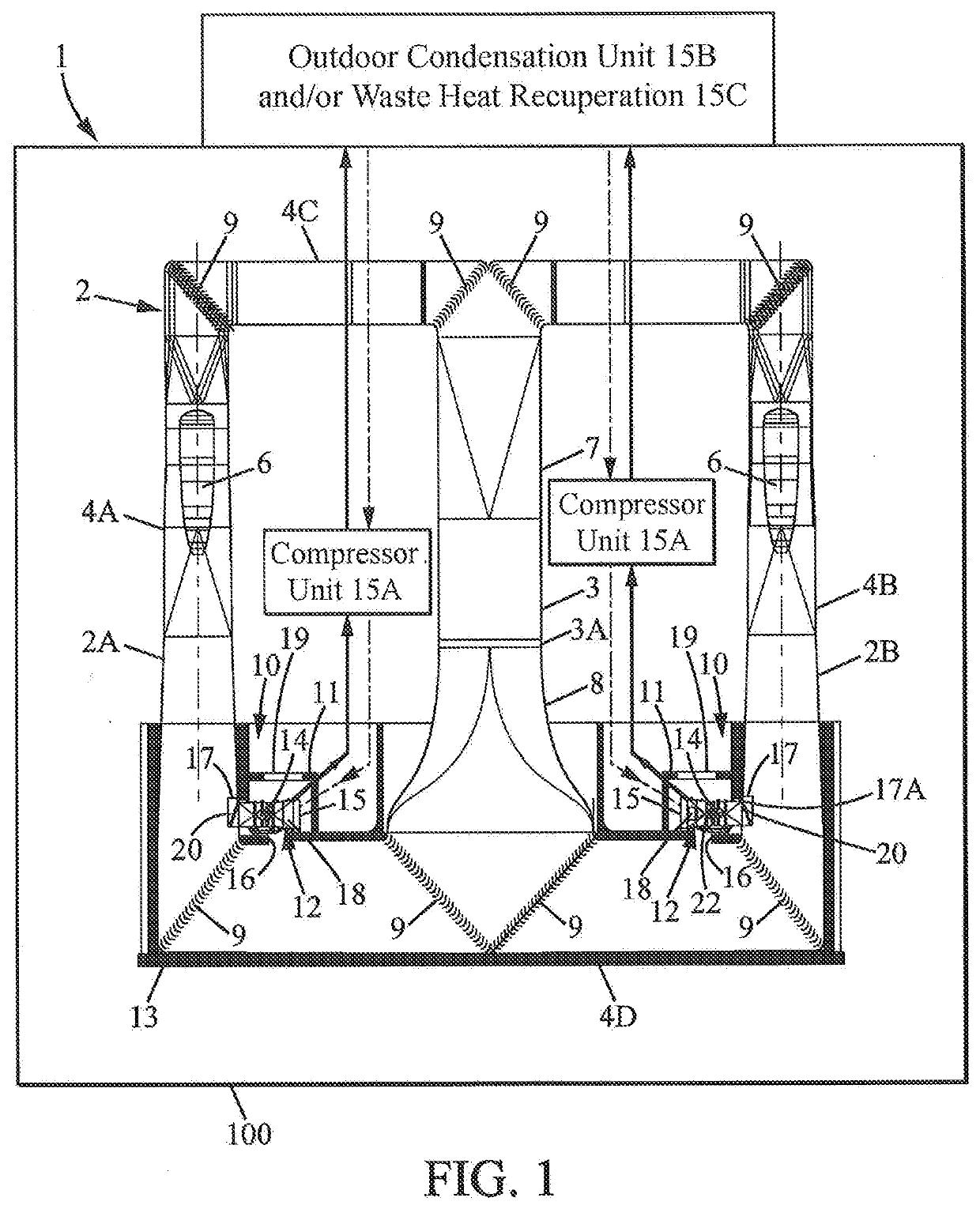
[0037]FIG. 1 illustrates an example of the free fall simulator 1, in accordance with the free fall simulator according to claim 1. The free fall simulator 1 is installed in building 100.

[0038]The free fall simulator according to FIG. 1 comprises a flight chamber 3 which is accessible to users of the simulator 1. At the bottom of the flight chamber 3 is installed a safety net 3A (made of metal wire for instance), which serves as the floor of the flight chamber 3. Air flows through the net 3A, from bottom to top, effecting the lifting of the user of the simulator 1 upwards, where the force of the upwards streaming air cancels out the gravitational force acting on the user.

[0039]The remaining parts of the simulator 1 that are connected to the flight chamber 3 and through which the air flows, are described as a wind tunnel system 2. Together, the wind tunnel system 2 and the flight chamber 3 then form a cyclic wind tunnel. Upwards from the flight chamber 3, in the direction of the airfl...


PUM


Abstract

A free fall simulator comprising: a wind tunnel system; a flight chamber connected to the wind tunnel system such that the wind tunnel system and the flight chamber allow for a continuous flow of circulating air, and a cooling system for cooling of the air circulating in the wind tunnel system, wherein the cooling system comprises: an air inlet sucking in a part of the air circulating in the wind tunnel system; at least one heat exchanger comprising a coolant: and at least one air outlet adapted such that the cooled air leaves the cooling system through the at least one air outlet. The cooling system further comprises: a closed pressure chamber comprising a cooling area, wherein pressure in said cooling area is higher than atmospheric pressure, and at least one auxiliary fan configured to maintain pressure within the cooling area of the pressure chamber higher than the atmospheric pressure, wherein the at least one heat exchanger is located inside of the closed pressure chamber so that the cooling of the circulating air takes place in the cooling area.

Description

FIELD OF TECHNOLOGY[0001]This invention focuses on improving existing free fall simulators, in particular on improvements in the circulating air cooling system of the simulator.BACKGROUND[0002]Similar free fall simulators, on which this invention expands, are already described, in the Czech utility model No. 2009-21805. These modern systems utilize an advantageous shape of the wind tunnel system in combination with an advantageous placement of the fans and they, and already disclose certain advantages connected to the use of an internal cooling system located inside the wind tunnel system.[0003]Further development in the field of free fall simulators has shown that despite the increased effectiveness of the above explained known free fall simulation systems there are still certain drawbacks, which could be addressed in order to achieve a free fall simulator offering higher comfort for a user as well as offering easier simulator integration into the surrounding building complexes, wh...

Claims


Application Information

Patent Timeline
Patent Type & Authority Applications(United States)
IPC IPC(8): A63G31/00F24F1/0059
CPCA63G31/00A63G2031/002F24F1/0059A63G2031/005B64D23/00
Inventor MARSIK, TOMAS
Owner STROJIRNA LITVINOV SPOL
Why Eureka
Try Eureka