Method for controlling an electric machine and drive system for a vehicle

a technology of electric machines and drive systems, applied in the direction of electric energy management, electric devices, transportation and packaging, etc., can solve the problems of increasing the range of vehicles, achieve the effect of reducing material costs of the first converter, reducing the maximum possible switching frequency, and increasing the switching loss

Pending Publication Date: 2021-04-22
DR ING H C F PORSCHE AG
View PDF6 Cites 0 Cited by
  • Summary
  • Abstract
  • Description
  • Claims
  • Application Information

AI Technical Summary

Benefits of technology

[0006]In the method, according to aspects of the invention, the first converter is operated with block commutation, as a result of which switching losses can be reduced. Undesired harmonics in the magnetic flux that are generated by the first converter, for example, can be compensated for in an order- or frequency-based manner by means of the second converter operated with pulse width modulation, in particular space vector modulation. Overall it thus becomes possible to increase the efficiency of the drive comprising the electric machine, such that the range of a vehicle driven by the machine can be increased.
[0010]One advantageous configuration provides for a clock frequency of the second converter to be set in such a way that the sum of the switching losses of the first and second converters is reduced, wherein undesired side effects, in particular noise, are preferably corrected according to defined criteria, in particular a weighting function. Alternatively or additionally, the clock frequency of the second converter is set in such a way that the harmonic losses are optimally corrected.
[0016]Preferably, the second converter comprises semiconductor switches having a higher maximum possible switching frequency than the first converter. As a result, semiconductor switches having higher switching losses can be used in the first converter and the material costs for the first converter can be reduced. Particularly preferably, the second converter comprises SiC or GaN semiconductor switches, for example SiC MOSFETs or GaN FETs. The first converter can comprise Si semiconductor switches, for example Si IGBTs.
[0017]In accordance with one advantageous configuration, provision is made for the drive system to comprise a common link circuit, in particular having a common link circuit capacitor, which is connected to the first converter and the second converter. A compact and cost-effective configuration of the drive system is made possible as a result.
[0020]Also described herein is a vehicle, in particular an electric vehicle or a hybrid vehicle, having a drive system described above. The same advantages as have already been described in association with the method for controlling an electric machine and the drive system can be achieved in the case of the vehicle.

Problems solved by technology

Against this background, the problem addressed is that of increasing the range of a vehicle driven by an electric machine.

Method used


Image

  • Method for controlling an electric machine and drive system for a vehicle
  • Method for controlling an electric machine and drive system for a vehicle
  • Method for controlling an electric machine and drive system for a vehicle

Examples


Embodiment Construction

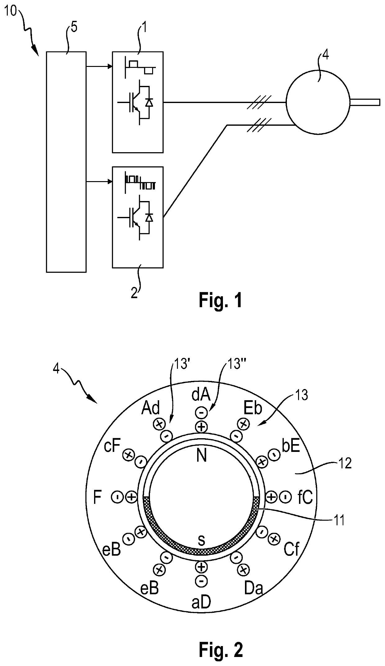
[0027]FIG. 1 illustrates a drive system 10, which is embodied as a traction drive system for a vehicle and which comprises an electric machine 4 embodied as a permanent magnet synchronous machine. The electric machine 4 is fed by two separate, in each case three-phase, winding systems. In this respect, the electric machine 4 comprises a first three-phase winding system and a second three-phase winding system.

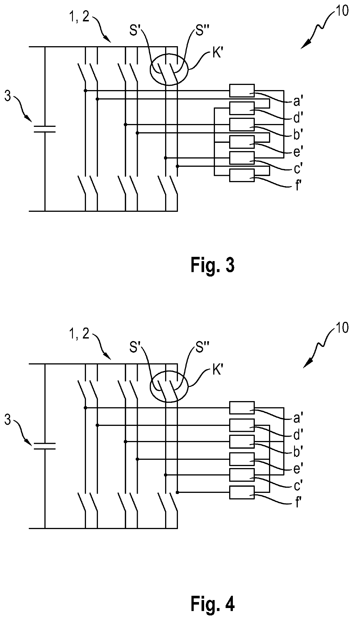
[0028]As further constituents of the drive system 10, a first converter 1 and a second converter 2 are provided, which are controlled by way of a control device 5 of the drive system 10. The first converter 1 is connected to the first winding system and the second converter 2 is connected to the second winding system. In order to reduce the switching losses of the converter 1 and thus to increase the range of the vehicle driven by the electric machine 4, the control device 5 is configured to operate the first converter 1 with block commutation and to operate the second converter...


PUM


Abstract

A method for controlling an electric machine, in particular a permanent magnet synchronous machine, having a first, in particular three-phase, winding system, which is controlled by a first converter, and having a second, in particular three-phase, winding system, which is controlled by a second converter. The first converter is operated with block commutation and the second converter is operated with pulse width modulation, in particular space vector modulation.

Description

CROSS-REFERENCE TO RELATED APPLICATION[0001]This application claims priority to German Patent Application No. 10 2019 128 473.2, filed Oct. 22, 2019, the content of such application being incorporated by reference herein in its entirety.FIELD OF THE INVENTION[0002]The invention relates to a method for controlling an electric machine, in particular a permanent magnet synchronous machine. Furthermore, the invention relates to a drive system, in particular a traction drive system, for a vehicle.BACKGROUND OF THE INVENTION[0003]In traction drive systems for an electric vehicle or a hybrid vehicle, permanent magnet synchronous machines are often used as electric machines. A converter is generally provided for controlling such machines, said converter providing the machine with a polyphase operating voltage. The converter is typically operated with space vector modulation (SVM). This method of operating the converter involves providing pulse-width-modulated operating voltages for the elec...

Claims


Application Information

Patent Timeline
Patent Type & Authority Applications(United States)
IPC IPC(8): H02P27/08H02P25/22B60W10/08B60L15/20
CPCH02P27/08H02P25/22B60L2220/56B60L15/20B60L2220/58B60W10/08H02M7/53875H02K3/12B60L15/007Y02T10/64Y02T10/72
Inventor WENDE, JOHANNESNELLES, ROBERTHUBERT, THOMAS
Owner DR ING H C F PORSCHE AG
Why Eureka
Try Eureka