
Rotating heat exchanger with improved heat transfer efficiency

a heat exchanger and rotary technology, applied in lighting and heating apparatus, ventilation systems, heating types, etc., can solve the problems of hygroscopic heat accumulation surfaces, unsatisfactory leakage, heat transfer and heat accumulation surfaces in such latent heat storage, etc., and achieve the effect of reducing manufacturing costs

Active Publication Date: 2021-04-29
FLEXIT SVERIGE AB
View PDF0 Cites 0 Cited by
  • Summary
  • Abstract
  • Description
  • Claims
  • Application Information

AI Technical Summary

Benefits of technology

This patent describes an improved heat transfer assembly for a rotor. By using cross-sectionals forms of channels in the rotor, the heat transfer efficiency is improved. This is especially useful when using materials with low thermal conductivity, such as a rotor matrix made of channels with a hexagonal shape. The rotor is made from a heat absorbent material with low thermal conductivity, which increases the efficiency of the rotor. Additionally, a foil material with low thermal conductivity and a corrugated top layer of high thermal conductivity may be used to reduce manufacturing costs. The technical effects of this invention are improved heat transfer and efficiency of the rotor.

Problems solved by technology

U.S. Pat. No. 4,200,441 discloses another winding method where the foil is made from corrugated strips, where the heat exchange is improved by an open communication between channels in neighboring layers, resulting in undesired leakage.
The latent heat is stored as moisture, and the heat transfer and heat accumulating surfaces in such latent heat storage are often hygroscopic, while the sensible heat is strictly absorbed by conductivity in the heat transfer and heat accumulating surfaces.

Method used


Image

  • Rotating heat exchanger with improved heat transfer efficiency
  • Rotating heat exchanger with improved heat transfer efficiency
  • Rotating heat exchanger with improved heat transfer efficiency

Examples


Embodiment Construction

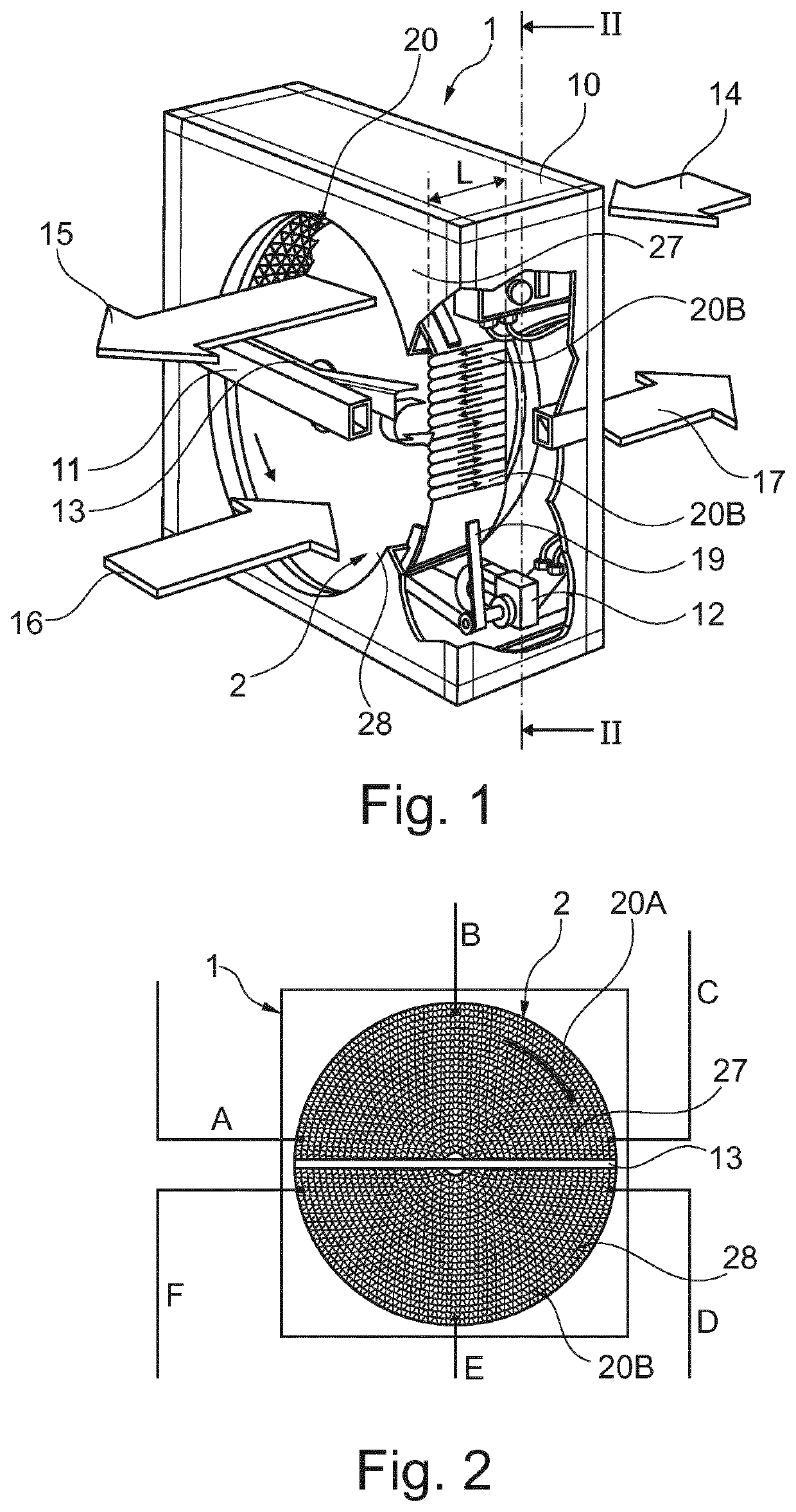
lass="d_n">[0075]In FIG. 1 there is shown a heat transfer assembly 1 for a rotary regenerative heat exchanger. This assembly includes a housing 10 and a support frame 11, supporting a rotor 2 arranged between at least two separated fluid flow passages 14 / 15, 16 / 17. The two fluid flow passages 14 / 15, 16 / 17 comprise an inflow 14 / 15 having incoming fresh air, outdoor air 14 passing the rotor 2 and leaving the rotor 2 as conditioned air, supply air 15, and an outflow 16 / 17 having outgoing air, extract air 16 passing the rotor 2 for heat exchange and finally leaving as expelled air, exhaust air 17.

[0076]The rotor 2 is normally driven at a continuous rotational speed of about 5-20 rpm. The drive may be a motor 12 driving a belt 19 arranged around the rotor 2. The two flows 14 / 15, 16 / 17, pass counter currently through the rotor 2. Each flow passage 14 / 15, 16 / 17 passes each one of a sector part 27 and 28 respectively of the rotor 2, separated by a partition wall 13, separating the two flows...


PUM

PropertyMeasurementUnit
Poweraaaaaaaaaa
Poweraaaaaaaaaa
Areaaaaaaaaaaa

Abstract

The disclosure relates to a heat transfer assembly for a rotary regenerative heat exchanger. The assembly includes a rotor arranged between at least two separated fluid flow passages passing flow axially through the rotor, where each flow passage is connected to a sector part of the rotor. The assembly further includes a plurality of channels in the rotor for flowing a fluid through the rotor, each of the channels is enclosed by heat transfer and heat accumulating surfaces in the rotor, and the heat transfer and heat accumulating surfaces of the channels are made in a material providing an average axial thermal conductivity less than 100 W / mK arranged to reduce the Longitudinal Heat Conductivity of the rotor.

Description

CLAIM FOR PRIORITY[0001]This application claims the benefit of priority to PCT / EP2018 / 077469, filed Oct. 9, 2018, which claims the benefit of priority to EP1751279-9, filed Oct. 13, 2017, the entire contents of which are hereby incorporated by reference.BACKGROUND OF THE DISCLOSURE[0002]The present disclosure relates to a rotary heat exchanger and ways to improve the heat transfer efficiency between the used air and the fresh air passing through the rotary heat exchanger.[0003]Rotary heat exchangers has been used since decades in climate systems where old air is ventilated off and replaced with fresh outdoor air. The rotatory heat exchanger is connected such that about 50% of the rotor body is exposed to flow of old air (extract air) and the other 50% of the rotor body is exposed to flow of fresh (outdoor air) air. Heat caught in the rotor in one half is transferred to the other flow by rotation of the rotor body.[0004]The main approaches used when trying to improve heat transfer ca...

Claims


Application Information

Patent Timeline
IPC IPC(8): F24F12/00F24F7/04F28D11/02F28D19/04F28F13/08F28F13/14F28F21/06F28F21/08
CPCF24F12/006F28F2270/00F28D11/02F28D19/044F28F13/08F28F13/14F28F21/063F28F21/066F28F21/081F24F2203/1008F24F2203/104F24F2203/1048F24F2203/1068F24F2203/108F24F7/04F28D19/042F24F2203/10Y02B30/56Y10S165/009F28D19/04
Inventor BIÖRKLUND, STAFFANHALFVARDSSON, ANNELILIU, PENG
Owner FLEXIT SVERIGE AB
Learn More