Organic light emitting diode and organic light emitting device including the same

a light-emitting diode and organic technology, applied in the direction of semiconductor devices, basic electric elements, electrical equipment, etc., can solve the problems of low luminous efficiency of conventional fluorescent materials, low luminous efficiency of blue phosphorescent materials, and short luminous lifetime of metal complexes as representative phosphorescent materials to be applicable into commercial devices, etc., to enhance luminous efficiency and lifetime, and reduce the driving voltage

Pending Publication Date: 2021-04-29
LG DISPLAY CO LTD
View PDF2 Cites 3 Cited by
  • Summary
  • Abstract
  • Description
  • Claims
  • Application Information

AI Technical Summary

Benefits of technology

[0007]An object of the present disclosure is to provide an OLED that can lower its driving voltage and to enhance its luminous efficiency and lifetime and an organic light emitting device including the diode.

Problems solved by technology

Conventional fluorescent materials have shown low luminous efficiency because only the singlet excitons are involved in the luminescence process thereof.
However, the metal complex as the representative phosphorescent material has too short luminous lifetime to be applicable into commercial devices.
Particularly, the blue phosphorescent material has showed low luminous efficiency and color purity.

Method used


Image

  • Organic light emitting diode and organic light emitting device including the same
  • Organic light emitting diode and organic light emitting device including the same
  • Organic light emitting diode and organic light emitting device including the same

Examples


example 1 (

Ex. 1): Fabrication of OLED

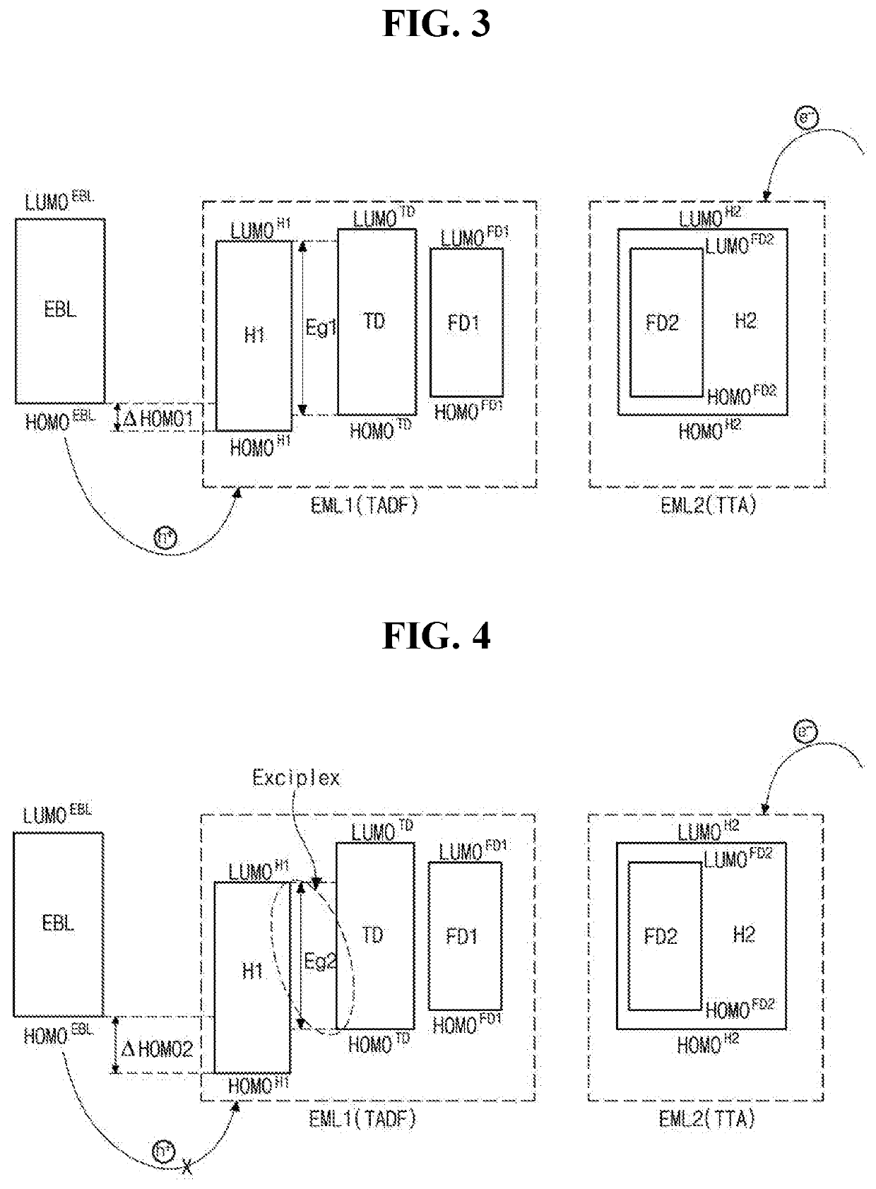
[0226]An OLED wherein a first EML (EML1) implements TADF and a second EML (EML2) implements a TTA was fabricated. The first EML includes Compound 1-1 in Chemical Formula 2 (2,6-di(9H-carbazol-9-yl)pyridine, 2,6-CzPy, LUMO: −2.6 eV; HOMO: −5.7 eV) as a first host (H1) and Compound 2-1 in Chemical Formula 4 (TDBA-DI, LUMO: −2.6 eV, HOMO: −5.5 eV) as the thermally activated delayed fluorescent material (TD). The second EML includes Compound 5-1 in Chemical Formula 10 (TBADN, LUMO: −2.6 eV, HOMO: −5.5 eV) as a second host (H2). Each of the first EML and the second EML includes Compound 3-1 in Chemical Formula 6 (DNBAN-2, LUMO: −2.8 eV, HOMO: −5.4 eV) as a fluorescent material, respectively. In addition, the EBL includes TAPC (LUMO: −2.0 eV, HOMO: −5.5 eV).

[0227]ITO substrate was washed by UV-Ozone treatment before using and loaded in an evaporation system. The ITO substrate was transferred to a vacuum chamber for depositing emissive layer. Subsequently, an ano...

example 2 (

Ex. 2): Fabrication of OLED

[0230]An OLED was fabricated using the same materials as Example 1, except that Compound 5-2 in Chemical Formula 10 (ADN, LUMO: −2.6 eV, HOMO: −5.8 eV) was used as the second host in the EML2 instead of TBADN.

example 3 (

Ex. 3): Fabrication of OLED

[0231]An OLED was fabricated using the same materials as Example 1, except that Compound 5-3 in Chemical Formula 10 (PADN) was used as the second host in the EML2 instead of TBADN.


PUM

PropertyMeasurementUnit
energy levelaaaaaaaaaa
energy level bandgap ΔESTTDaaaaaaaaaa

Abstract

An organic light emitting diode (OLED) includes a first emitting material layer disposed adjacently to a first electrode and a second emitting material layer disposed adjacently to a second electrode. The first emitting material layer includes a first compound having high affinity to holes and a second compound of thermally activated delayed fluorescent material, and the second emitting material layer includes a fourth compound having high affinity to electrons and implementing triplet-triplet annihilation. Two emitting material layers having adjusted energy levels allow the OLED to lower its driving voltages and improve its luminous efficiency and luminous lifetime.

Description

CROSS-REFERENCE TO RELATED APPLICATIONS[0001]This application claims the benefit under 35 U.S.C. § 119(a) to Korean Patent Application No. 10-2019-0133040, filed in the Republic of Korea on Oct. 24, 2019 and Korean Patent Application No. 10-2020-0113939, filed in the Republic of Korea on Sep. 7, 2020, the entire contents of all these applications are incorporated herein by reference in its entirely into the present application.BACKGROUNDTechnical Field[0002]The present disclosure relates to an organic light emitting diode, and more specifically, to an organic light emitting diode having excellent luminous properties and an organic light emitting device having the organic light emitting diode.Discussion of the Related Art[0003]An organic light emitting diode (OLED) has come into spotlight as a light emitting diode rapidly replacing a liquid crystal display device (LCD). The OLED can be formed as a thin film having a thickness less than 2000 Å and can be implement unidirectional or bi...

Claims


Application Information

Patent Timeline
Patent Type & Authority Applications(United States)
IPC IPC(8): H01L51/00
CPCH01L51/0073H01L51/0072H01L51/5004H01L51/0059H01L51/0054H10K85/615H10K85/622H10K85/654H10K85/657H10K85/6572H10K50/11H10K2101/40H10K50/121H10K50/13H10K2101/10H10K85/626H10K85/322H10K50/19H10K2101/20H10K85/6574H10K85/631H10K50/18
Inventor RYU, HYE-GUNCHOE, IK-RANGKIM, JUN-YUNKIM, SEONG-KEUNLEE, JU-YOUNG
Owner LG DISPLAY CO LTD
Why Eureka
Try Eureka