Heating apparatus and chemical vapor deposition system

Active Publication Date: 2021-05-06
PLAYNITRIDE DISPLAY CO LTD
View PDF16 Cites 0 Cited by
  • Summary
  • Abstract
  • Description
  • Claims
  • Application Information

AI Technical Summary

Benefits of technology

The invention is about a heating apparatus that can make the temperature of a substrate even. There are two heaters in this system, and their widths are different. This design helps to make the substrate temperature even, resulting in a more uniform film thickness and light emission from the substrate. Overall, this improves the quality of the final product.

Problems solved by technology

To satisfy performance specifications under various different usage requirements, light-emitting diode elements of different structures or materials continuously challenge design and mass production capabilities of relevant manufacturers.
However, as the size of the epitaxial substrate increases and the size of the light-emitting diode element decreases, the traditional CVD device can no longer satisfy the temperature uniformity requirement of the epitaxial substrate during film formation.

Method used


Image

  • Heating apparatus and chemical vapor deposition system
  • Heating apparatus and chemical vapor deposition system
  • Heating apparatus and chemical vapor deposition system

Examples


first embodiment

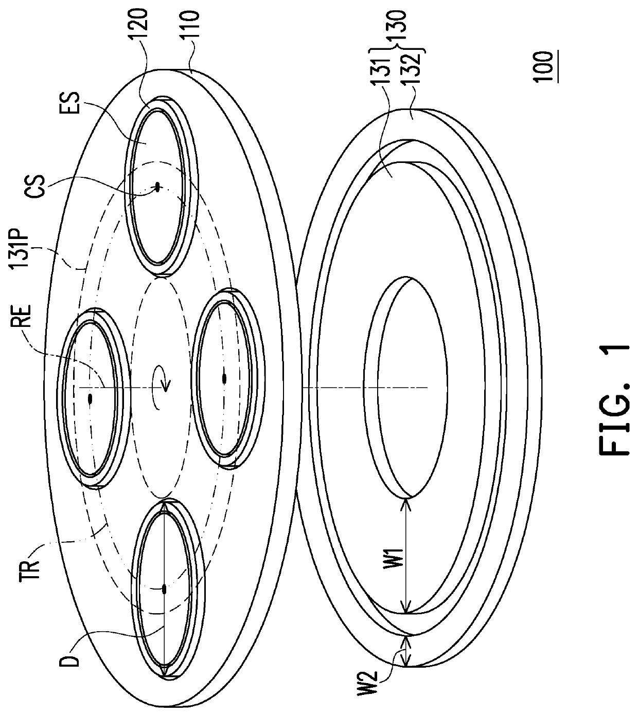
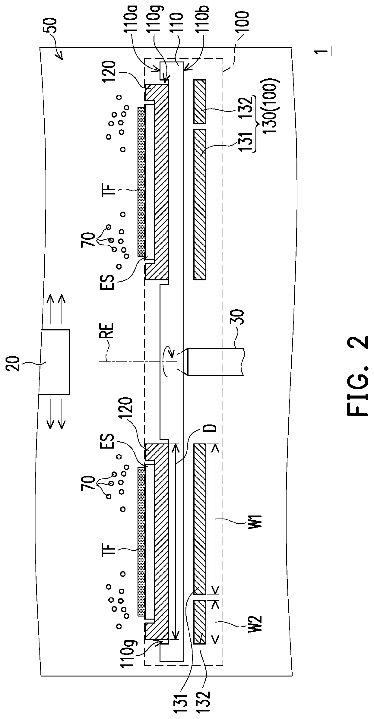
[0034]FIG. 1 is a schematic partial exploded view of a heating apparatus according to the invention. FIG. 2 is a schematic cross-sectional view of a CVD system according to an embodiment of the invention. Referring to FIG. 1 and FIG. 2, the CVD system 1 includes a chamber 50, a heating apparatus 100, an air inlet unit 20, and a rotation driving mechanism 30. The heating apparatus 100 includes a rotating stage 110, a plurality of wafer carriers 120, and a heater 130. The wafer carrier 120 is configured to position an epitaxial substrate ES on the rotating stage 110. The wafer carrier 120 and the heater 130 are respectively disposed on two opposite sides of the rotating stage 110. Specifically, the rotating stage 110 includes a first surface 110a and a second surface 110b that are opposite and a plurality of grooves 110g provided on the first surface 110a. These wafer carriers 120 are respectively disposed in these grooves 110g and protruding from the first surface 110a of the rotatin...

second embodiment

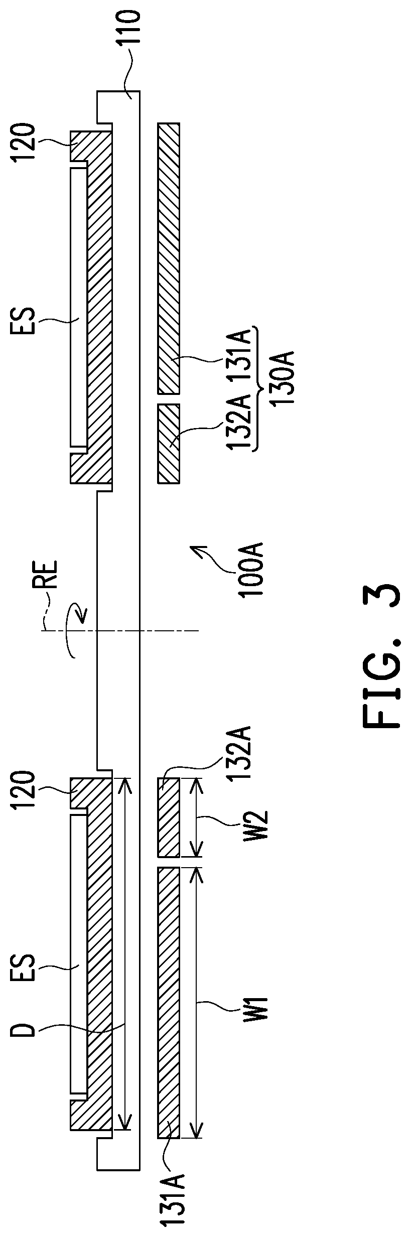
[0041]FIG. 3 is a schematic cross-sectional view of a heating apparatus according to the invention. Referring to FIG. 3, a main difference between the heating apparatus 100A in the present embodiment and the heating apparatus 100 in FIG. 2 is that the heater is configured in different manners. Specifically, in the radial direction of the rotating stage 110, a second heater 132A of a heater 130A is located between a first heater 131A and the rotating axis RE. In the present embodiment, a configuration relationship between the first heater 131A and the wafer carrier 120 is similar to that of the heating apparatus 100 in the foregoing embodiment, and the descriptions thereof are omitted herein.

[0042]It is specially noted that, a ratio of a first width W1 of the first heater 131A to the wafer carrier diameter D of the wafer carrier 120 is greater than 0.5 and less than 1. Therefore, the first heater 131A may heat only a partial region of the wafer carrier 120, helping improve temperatur...

third embodiment

[0043]FIG. 4 is a schematic cross-sectional view of a heating apparatus according to the invention. Referring to FIG. 4, a main difference between the heating apparatus 100B in the present embodiment and the heating apparatus 100 in FIG. 2 is that the number of the heaters is different. In the present embodiment, the heating apparatus 100B further includes a third heater 133, and in the radial direction of the rotating stage 110, the third heater 133 is located between the first heater 131 and the rotating axis RE. The first heater 131, the second heater 132, and the third heater 133 are separated from one another, and the third heater 133 does not overlap the wafer carrier 120 in the axial direction of the rotating axis RE. In this way, a capability of a heater 130B for adjusting temperature distribution of the epitaxial substrate ES in the radial direction can be improved. In the present embodiment, a configuration relationship between the first heater 131, the second heater 132, ...


PUM

PropertyMeasurementUnit
Temperatureaaaaaaaaaa
Diameteraaaaaaaaaa
Ratioaaaaaaaaaa

Abstract

A heating apparatus including a rotating stage, a plurality of wafer carriers, a first heater, and a second heater is provided. The rotating stage includes a rotating axis. The plurality of wafer carriers is disposed on the rotating stage. The rotating stage drives the wafer carriers to rotate on the rotating axis. The first heater is disposed under the rotating stage. The first heater includes a first width in a radial direction of the rotating stage. The second heater is disposed under the rotating stage. The second heater and the first heater are separated from each other. The second heater includes a second width in the radial direction of the rotating stage, and the first width is not equal to the second width. A chemical vapor deposition (CVD) system using the heating apparatus is also provided.

Description

CROSS-REFERENCE TO RELATED APPLICATION[0001]This application claims the priority benefits of Taiwan application serial no. 108140233, filed on Nov. 6, 2019, and Taiwan application serial no. 108140232, filed on Nov. 6, 2019. The entirety of each of the above-mentioned patent applications is hereby incorporated by reference herein and made a part of this specification.BACKGROUND OF THE INVENTIONField of the Invention[0002]The disclosure relates to a film deposition apparatus, and in particular, to a heating apparatus and a chemical vapor deposition (CVD) system.Description of Related Art[0003]With continuous improvements in operating performance and reliability of light-emitting diode materials, the light-emitting diode materials are gradually applied to diversified fields, for example, lighting devices, displays, and backlight modules. To satisfy performance specifications under various different usage requirements, light-emitting diode elements of different structures or materials ...

Claims


Application Information

Patent Timeline
IPC IPC(8): C23C16/46C23C16/458
CPCC23C16/46H01L33/005C23C16/4584C23C16/4586
Inventor WU, JYUN-DELAI, YEN-LINCHEN, CHI-HENG
Owner PLAYNITRIDE DISPLAY CO LTD
Why Eureka
Try Eureka